Concrete crack inhibiting device

a crack inhibiting device and concrete technology, applied in the direction of girders, building repairs, manufacturing tools, etc., can solve the problems of stress cracks, high cracks and fractures emanating from the re-entrant corners, and serious construction problems in the building industry. , to achieve the effect of sufficient structural integrity

Active Publication Date: 2014-05-20
SCHMITZ PAUL W
View PDF22 Cites 7 Cited by
  • Summary
  • Abstract
  • Description
  • Claims
  • Application Information

AI Technical Summary

Benefits of technology

[0010]The implanted or embedded re-entrant concrete crack inhibiting device of this invention, in effect, creates an internally disposed channeling pathway (e.g. in the form of a radial arm) within which the energy of potential stress fractures emanating from the re-entrant corner are effectively channeled and ultimately intercepted by a fracture intercepting unit. The fracture intercepting unit is sized and positioned in a transverse relationship to the radial arm so as to intercept, retard, and interrupt any substantive development of stress fracturing about the casted concrete re-entrant corner.
[0011]To effectively withstand the internal forces crated by the extreme weight of wet concrete mix, the crack inhibiting device necessarily possess sufficient structural integrity so as to maintain its structural integrity and crack inhibiting efficacy in a poured formed concrete structure such as a formed concrete wall, floor or ceiling. A radially extending brace provides a radial brace bridging between the re-entrant corner brace and the stress fracture intercepting plate so as to brace the intercepting plate against collapse due to the weighted forces exerted upon the brace by the wet concrete mix. Further stabilization of the re-entrant corner from stress fractures may be achieved by inserting longitudinal radial intercepting members (such as re-enforcement rods, wires, etc.) to transverse a radii served by the fracture intercepting plate.
[0012]After the concrete slab has adequately cured, the implanted device (permanently embedded re-entrant concrete corner) may conveniently detached from the concrete forming frame or form to provide a concrete slab containing the re-entrant corner crack inhibiting device permanently implanted or embedded within cured concrete slab (e.g. such as wall or floor). The device effectively and permanently performs its intended function to retard and inhibit further fracturing or cracking about the re-entrant concrete corner and emanating beyond the intercepting plate.

Problems solved by technology

Stress fractures emanating from re-entrant concrete corners (i.e. inside corners) of a cured or dry concrete structure present serious construction problems to the building industry.
Such stress cracks occur as shrinkage stresses develop at the re-entrant corners of the concrete slab.
As the magnitude of the transformation from a wet to a cured or dry concrete structure, the stress concentration at the re-entrant corners within a concrete slab dramatically increases which results in a high incidence of cracks and fracturing emanating from the re-entrant corners.
These cracks are not only unsightly but can result in substantial structural damage.
Unfortunately, corrective reconstruction of structural damaging stress fractures may no only be monetarily costly but also costly in time and effort.
While the corner chipping has sporadically reduced or minimized the formation of re-entrant corners stress cracks, such chipping is time consuming and has not proven entirely satisfactory in substantially eliminating the formation of cracks at the re-entrant corners of a concrete slab.
Although this technique was purportedly useful in providing prefabricated walls, the creation of a cylindrical cavity at the re-entrant corners was further compounded by requiring corner extension inserts so as to provide the desired square corner structure at the re-entrant corner, all of which added labor and material costs to the construction as well as detracting from the structural utility and strength of the conventional concrete re-entrant corners of a unititary construction.
Due to its externally disposed position and small size, the Crews et al device fails to provide the overall prerequisites and efficacy as required to overcome the creation of stress fractures and structurally damaging cracks emanating from the re-entrant corners of concrete slabs.

Method used


Image

  • Concrete crack inhibiting device
  • Concrete crack inhibiting device
  • Concrete crack inhibiting device

Examples


Embodiment Construction

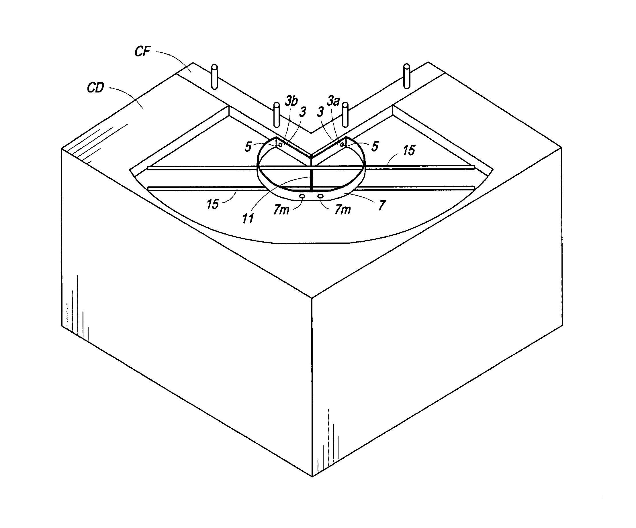
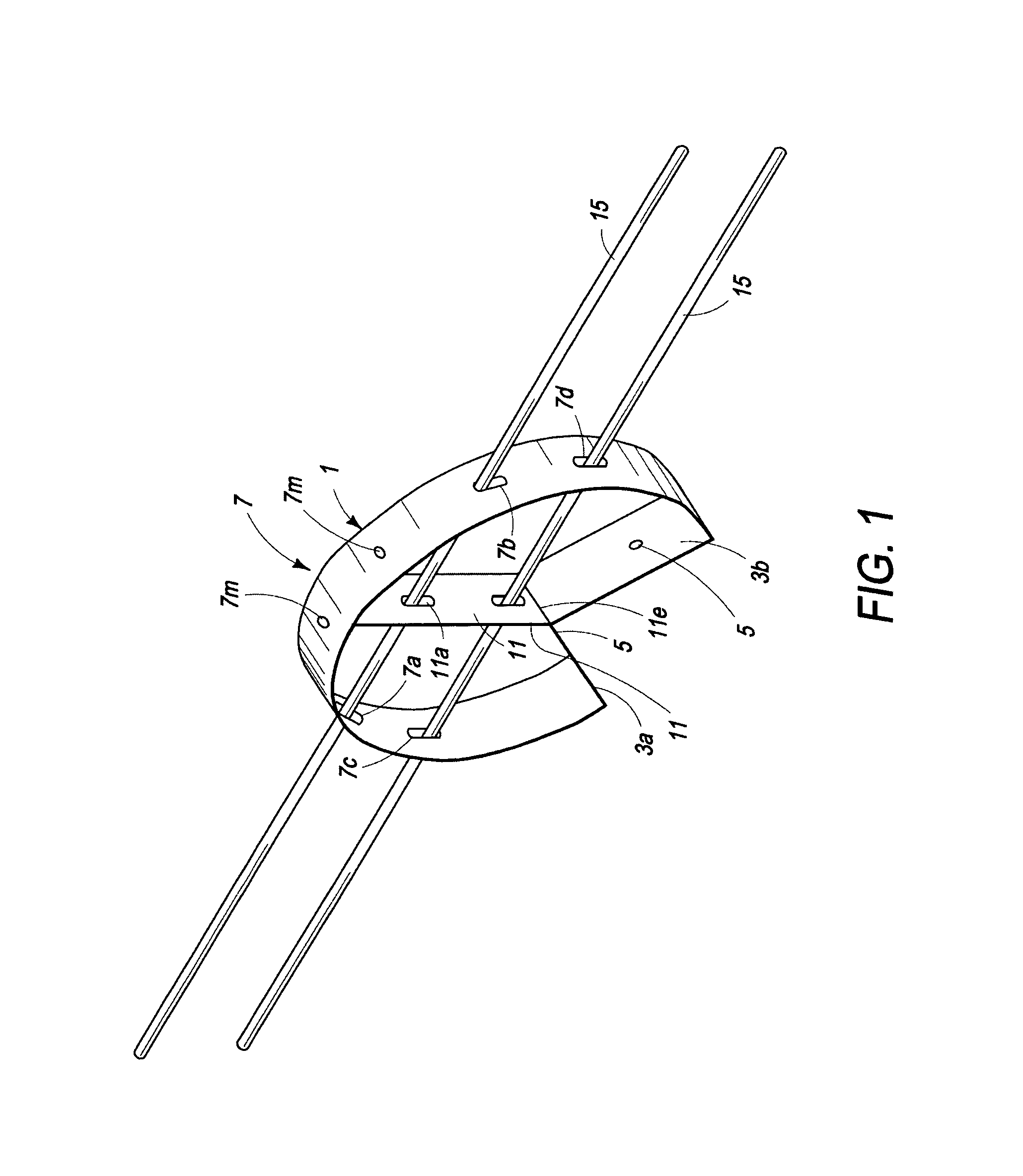
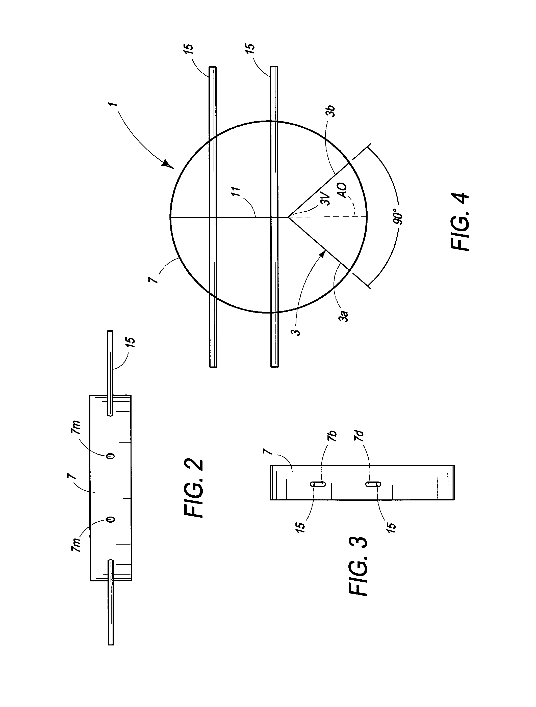
[0032]With reference to the Figures, the present invention provides a concrete crack inhibiting device 1 for use in inhibiting stress fractures from developing at re-entrant corners RC of concrete structures CD such as commonly arising in poured concrete walls W, floors F, ceilings, etc. The device 1 consists essentially of (a) a mountable re-entrant corner brace 3 equipped with corner mounts 5 for mounting the corner brace 3, and (b) a stress fracture intercepting plate 7 structurally supported by the re-entrant corner brace 3 and radially positioned about said corner brace 3 so as to intercept and retard stress fractures from radiating outwardly from a casted re-entrant concrete corner when the device 1 is implanted therewithin. The cornering brace 3 effectively serves as a base structure for structurally supporting a radial extending arm 11 and the stress fracture intercepting plate 7. The intercepting plate 7 is sized and positioned in a transverse relationship to stress fractur...


PUM

PropertyMeasurementUnit
lengthaaaaaaaaaa
bisecting angleaaaaaaaaaa

Abstract

A concrete re-entrant corner crack inhibiting device for implantation into a re-entrant corner of a casted concrete structure serves to inhibit stress fractures from developing at the cured concrete re-entrant corners. The device includes a re-entrant corning brace for cornering and embedding onto the re-entrant corner, a radial arm radiating outwardly from the brace so to extend into the cement structure and a fracture interrupting unit transversely connected to the radial arm so as to intercept, interrupt and inhibit the development and spread of stress fractures emanating from a cured cement re-entrant corner.

Description

[0001]This application is a non-provisional application of earlier filed provisional application No. 61 / 399,247, entitled “Concrete Crack Inhibiting Device”, filed on behalf of Paul W. Schmitz, on Jul. 8, 2010, the contents of which are incorporated by reference herein.FIELD OF INVENTION[0002]The present invention relates to stress fracture retardation and more particularly to a device for inhibiting stress fracture from developing at re-entrant corners of concrete structures, concrete structures containing the device and the method of its use.BACKGROUND OF THE INVENTION[0003]Stress fractures emanating from re-entrant concrete corners (i.e. inside corners) of a cured or dry concrete structure present serious construction problems to the building industry. Such stress cracks occur as shrinkage stresses develop at the re-entrant corners of the concrete slab. As the magnitude of the transformation from a wet to a cured or dry concrete structure, the stress concentration at the re-entra...

Claims


Application Information

Patent Timeline
Patent Type & Authority Patents(United States)
IPC IPC(8): E02D27/32E04F13/06E04C5/00E04B1/00
CPCE02D27/32B28B23/02B28B23/022E04C5/06E04G21/185
Inventor SCHMITZ, PAUL, W.
Owner SCHMITZ PAUL W
Why Eureka
Try Eureka