Method and apparatus for maintaining compression of the active area in an electrochemical cell

Inactive Publication Date: 2003-01-30
PROTON ENERGY SYST
View PDF4 Cites 17 Cited by
  • Summary
  • Abstract
  • Description
  • Claims
  • Application Information

AI Technical Summary

Benefits of technology

0066] Features of the cell collector plate disclosed herein include improved flexibility, flow field feature support and substantial uniformity of current conduction and heat conduction. These plates may function as current collectors providing electrical continuity between the fuel cell voltage terminals and electrodes. The foil sheets additionally provide mechanical support for the MEA and distribute the reactants and water across the active area of the MEA electrodes, wh

Problems solved by technology

Even in the absence of a protective casing or a separator plate, it nonetheless remains difficult to manufacture pressure pad

Method used


Image

  • Method and apparatus for maintaining compression of the active area in an electrochemical cell
  • Method and apparatus for maintaining compression of the active area in an electrochemical cell
  • Method and apparatus for maintaining compression of the active area in an electrochemical cell

Examples


example 2

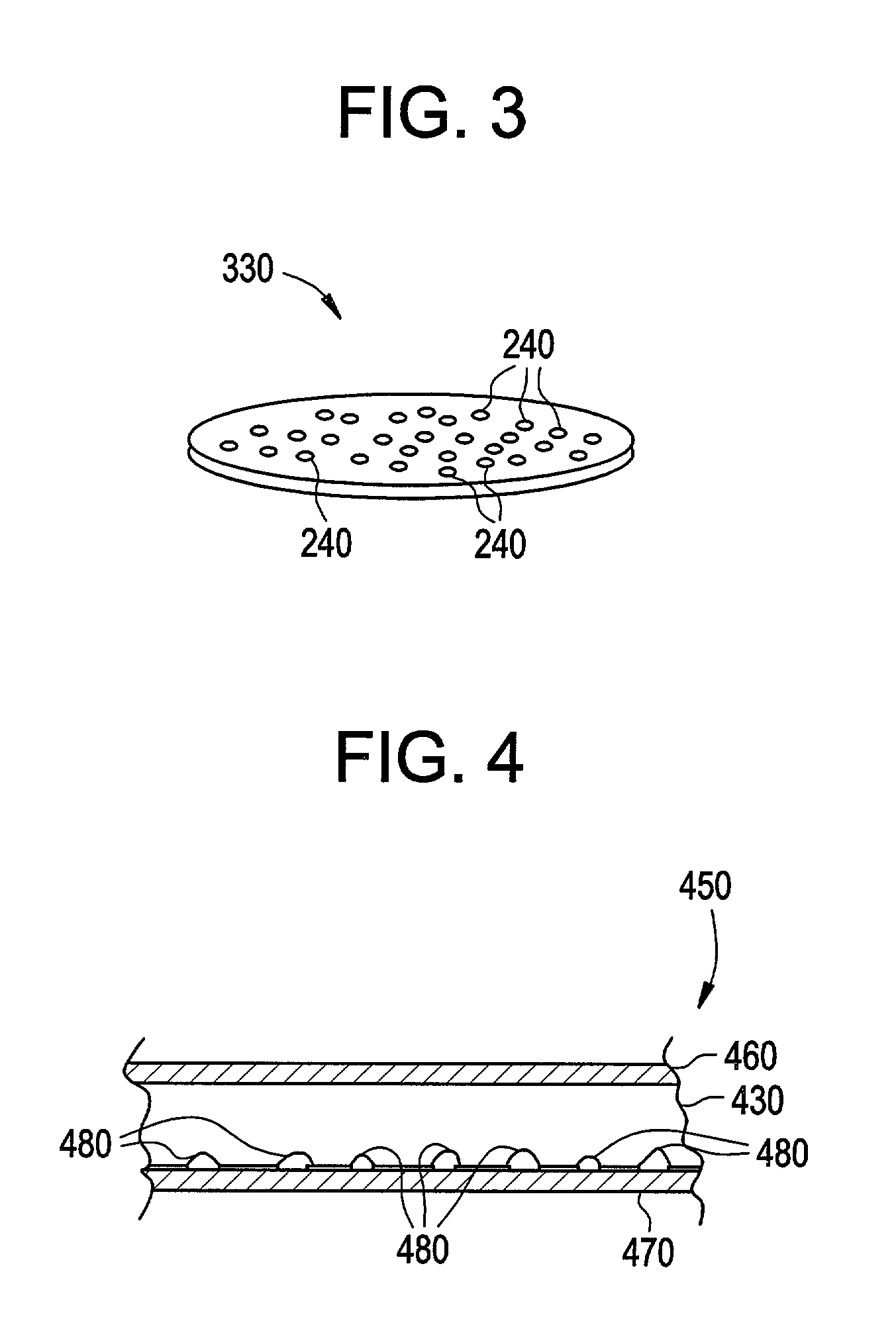
[0074] Pressure pad 340 is formed of a mixture of 50 wt. % VITON.RTM. and 50 wt. % niobium. The VITON.RTM. is in the form of cut up pieces of a 50 gauge cord having a diameter of about 0.125 inches (about 3.175 mm) and lengths of about 0.25 inches (about 6.35 mm)]. The niobium is in the form of cut up pieces having a minimum dimension of about 0.125 inches (about 3.175 mm) and a maximum dimension of about 0.25 inches (about 6.35 mm). The VITON.RTM. and niobium were mixed thoroughly and placed on a suitable sintering and pressing fixture having a diameter of about 1 inch (2.54 centimeters). The fixture was subjected to a pressure of 2000 psi and a temperature of 400.degree. F. The sintered plate comprises an integrated mixture of VITON.RTM. and niobium having a thickness of about 0.25 inches (about 6.35 mm), and suitable for use in a system having operating pressures between ambient pressure and up to about 10,000 psi.

example 3

[0075] Pressure pad 340 is formed of a mixture of 50 wt. % VITON.RTM. and 50 wt. % niobium. The VITON.RTM. is in the form of cut up pieces of a 50 gauge cord having a diameter of about 0.125 inches (about 3.175 mm) and lengths of about 0.25 inches (about 6.35 mm)]. The niobium is in the form of cut up pieces having a minimum dimension of about 0.125 inches (about 3.175 mm) and a maximum dimension of about 0.25 inches (about 6.35 mm). The VITON.RTM. and niobium were mixed thoroughly and placed on a suitable sintering and pressing fixture having a diameter of about 5 inches (12.7 centimeters). The fixture was subjected to a pressure of 2000 psi and a temperature of 400.degree. F. for 20 minutes wherein the temperature ramping was allowed to overshoot by 2.5.degree. F. for a period of 10 minutes. The sintered plate comprises an integrated mixture of VITON.RTM. and niobium having a thickness of about 0.2 5 inches (about 6.35 mm), and suitable for use in a system having operating pressur...

example 4

[0076] A number of unitary pressure pads were tested as follows: a silicone pressure pad comprising small carbon and nickel fibers (4.25 inch diameter, 0.33 inches (0.81 mm thick)) having a void volume of 48.2% was placed in a test device and subjected to a load of 35 inch-pounds, and a current of 25-2000 Amps was passed through the pad. Resistivity was calculated from the current and voltage. Results of the comparative tests are shown in FIG. 5. As can be seen from these results, elastomeric pressure pads comprising particulate Ag / Al, Ag / glass, Ag / Cu, Ag / Cu (3 hours at 150 amps), and Ni / C fillers (Tests 1, 3, 5, 5a, and 6, respectively) demonstrated low resistivities over a range of current densities from 25 to 175 Amps. Comparative test 2 is a pressure pad using niobium strips threaded through an elastomeric pressure pad. While this pad also has low resistivities, the niobium is not integral to the pad and the pad does not have a smooth surface.

[0077] The electrochemical cell desc...


PUM

PropertyMeasurementUnit
Fractionaaaaaaaaaa
Fractionaaaaaaaaaa
Fractionaaaaaaaaaa

Abstract

In one embodiment, the electrochemical cell comprises: a first electrode, a second electrode, and a membrane disposed between and in ionic communication with the first electrode and the second electrode. A first flow field is in fluid communication with the first electrode and disposed opposite the membrane, with a second flow field in fluid communication with second electrode and disposed opposite the membrane, and an electrically conductive pressure pad adjacent the first flow field and the first electrode. The pressure pad comprises a mixture of at least one substoichiometric oxide of titanium and an elastomeric material.

Description

[0001] This application is a continuation in-part of U.S. patent application Ser. No. 09 / 965,680, filed on Sep. 27, 2001, which claims priority to U.S. Application Serial No. 60 / 235,757, filed Sep. 27, 2000, which are fully incorporated herein by reference.BACKGROUND OF INVENTION[0002] The present disclosure relates to a method and apparatus for maintaining compression within the active area of an electrochemical cell.[0003] Electrochemical cells are energy conversion devices, usually classified as either electrolysis cells or fuel cells. A proton exchange membrane electrolysis cell can function as a hydrogen generator by electrolytically decomposing water to produce hydrogen and oxygen gas, and can function as a fuel cell by electrochemically reacting hydrogen with oxygen to generate electricity. Referring to FIG. 1, which is a partial section of a typical anode feed electrolysis cell 100, process water 102 is fed into cell 100 on the side of an oxygen electrode (anode) 116 to form...

Claims


Application Information

Patent Timeline
IPC IPC(8): C25B9/19C25C7/04H01M4/86H01M8/02H01M8/10H01M8/24
CPCC25B9/04C25B9/18H01M8/247H01M8/248H01M2008/1095Y02E60/50C25B9/65C25B9/70
Inventor ANDERSON, EVERETTHANLON, GREGORY A.SKOCZYLAS, THOMAS
Owner PROTON ENERGY SYST
Why Eureka
Try Eureka