
Position adjustable tactical light structure for long gun

a long gun and adjustable technology, applied in the field of tactical light technology, can solve the problems of inconvenient adjustment of mounting angle, troublesome mounting and detachment,

Active Publication Date: 2021-04-15
SHENZHEN OLIGHT E COMMERCE TECH CO LTD
View PDF0 Cites 7 Cited by
  • Summary
  • Abstract
  • Description
  • Claims
  • Application Information

AI Technical Summary

Benefits of technology

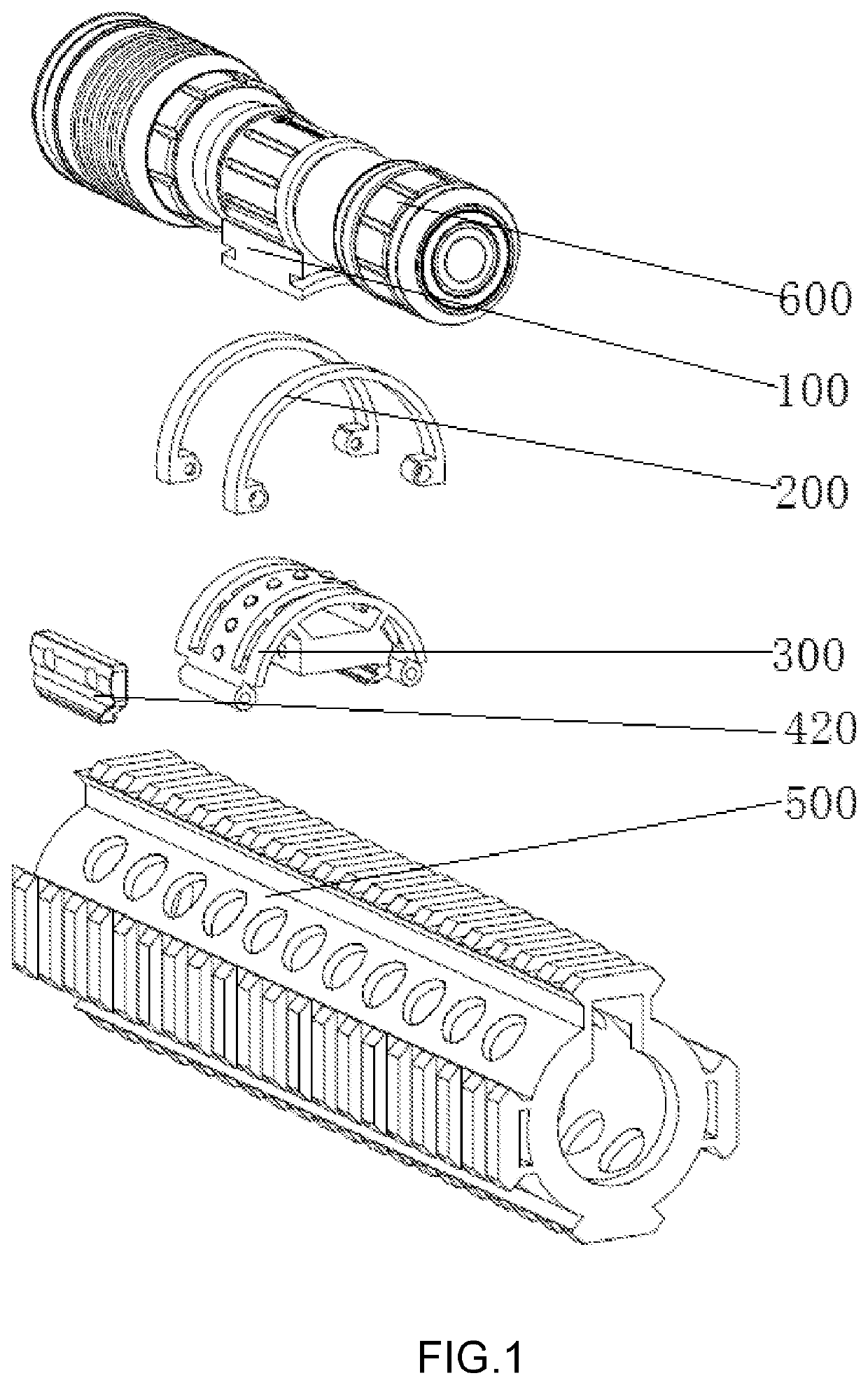
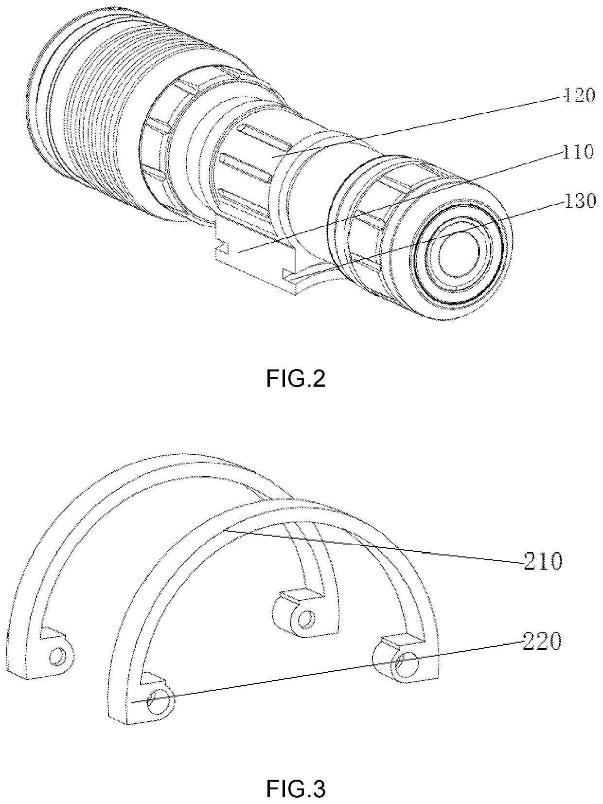
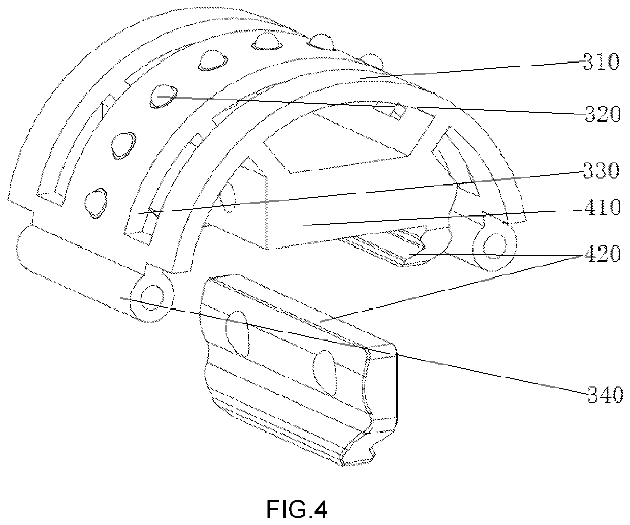
The present invention provides a position adjustable tactical light structure for long gun that can adjust the mounting angle of the tactical light on the firearm rail. This prevents the tactical light from affecting the line of sight after the tactical light is mounted on the barrel. By sliding slots and connecting strips on the base and support, as well as rivet connections between the fixing rings and the support or movable lock blocks and the fixing block, the tactical light can be conveniently mounted at different angles and easily replaced if damaged. The curved surface of the base also enhances the cooperation between the contact beads and the groove.

Problems solved by technology

In this way, mounting and detaching are relatively troublesome, and it is inconvenient to adjust the mounting angle; besides, other tools are required for adjusting the mounting angle of the tactical light.

Method used


Image

  • Position adjustable tactical light structure for long gun
  • Position adjustable tactical light structure for long gun
  • Position adjustable tactical light structure for long gun

Examples


Embodiment Construction

[0029]An embodiment of the present invention is further described in detail below. The embodiment is illustrated in the figures. Identical or like references throughout the description and the figures represent identical or like components or components having the same or similar functions. The embodiment described below with reference to the figures should be considered illustrative for the purpose of explaining the technical features of the present invention, and should not be considered as any limitation to the present invention.

[0030]In the present invention, it should be noted that directions or positional relationships indicated by terms such as “length”, “width”, “upper”, “lower”, “front”, “rear”, “left”, “right”, “vertical”, “horizontal”, “top”, “bottom”, “inner”, “outer” should be understood based on the directions or positional relationships according to the figures, and should also be understood as merely means for simplification for the sake of easier illustration of the...


PUM


Abstract

This invention includes a first clamping means which comprises a base and a clamp for mounting a portable lighting apparatus; the clamp is mounted on a first end surface of the base; sliding slots are formed on two opposite side walls of the base; a second end surface of the base is provided with a groove; fixing rings, each of which comprises a connecting strip and first fixing members provided at two ends of the connecting strip; the connecting strips are mounted on the sliding slots for the base to slide on the fixing rings; a support comprising a body and a plurality of contact beads; the plurality of contact beads are mounted on the body by elastic members; a second clamping means comprising a fixing block and movable lock blocks mounted on two sides of the fixing block; the fixing block is mounted on the support.

Description

BACKGROUND OF THE INVENTION[0001]The present invention belongs to the technical field of tactical light technology and relates to a position adjustable tactical light structure for long gun.[0002]During use of a common tactical light for long gun, when it is necessary to mount a sight on the barrel at a position on the same rail for mounting the tactical light, the tactical light would affect the line of sight. In the prior art, adjustment of the positon of the tactical light is mainly achieved by using two different types of bases. When it is necessary to mount the tactical light in middle position, use the middle base; when it is necessary to mount the tactical light on the side, use the base mounted on the side. In this way, mounting and detaching are relatively troublesome, and it is inconvenient to adjust the mounting angle; besides, other tools are required for adjusting the mounting angle of the tactical light.BRIEF SUMMARY OF THE INVENTION[0003]In view of the aforesaid disad...

Claims


Application Information

Patent Timeline
Patent Type & Authority Applications(United States)
IPC IPC(8): F41G11/00
CPCF41G11/003F41C27/00F21V33/00F41G1/387F41G11/008
Inventor MA, QIANGZHOU, ZIYANG
Owner SHENZHEN OLIGHT E COMMERCE TECH CO LTD
Learn More