Anti-blinding system for a vehicle

a technology of night vision and vehicle, applied in the field of night vision systems, can solve the problems of adding costs and complexity to adding costs and complexity associated with the thermal control of the laser, and further adding costs, so as to prevent the blinding of oncoming vehicles, reduce the cost and complexity of the night vision system, and minimize the field of view degradation

Inactive Publication Date: 2006-07-06
FORD GLOBAL TECH LLC
View PDF4 Cites 46 Cited by
  • Summary
  • Abstract
  • Description
  • Claims
  • Application Information

AI Technical Summary

Benefits of technology

[0012] The embodiments of the present invention provide several advantages. One such advantage is the provision of a night vision system that utilizes a selective attenuation filter to illuminate selected areas forward of a vehicle. In so doing, the present invention eliminates the need for utilizing a laser, a fan optic, and other thermal control and filter control electronics commonly associated with such devices. Thus, night vision system costs and complexity are reduced.
[0013] Another advantage that is provided by an embodiment of the present invention is the provision of selectively illuminating areas forward of a vehicle utilizing illumination generated from the headlamps of a vehicle or from the laser of a night vision system. The present invention prevents the directing of an illumination beam and / or provides the attenuation of selected portions of the illumination beam that are directed at nearby vehicles and objects. This prevents degradation to or obstruction of the field-of-view of a nearby vehicle operator or pedestrian. This selective illumination also: minimizes the field-of-view degradation due to the reflection of illumination beams through side view or rear view mirrors of a vehicle; allows the headlamps of a vehicle to continuously be operated in a “high-beam” mode without degradation to the field-of-view of an oncoming vehicle operator; and prevents the blinding of oncoming vehicle night vision systems.
[0014] Furthermore, the present invention provides an active night vision system that is inexpensive, versatile, and robust. The present invention also increases vehicle-operating safety by providing an improved view of an operating environment for both a host vehicle and any vehicles detected by the host vehicle.

Problems solved by technology

However, the use of a laser and a corresponding filter can add costs and complexity to a night vision system.
In addition to the laser and filter component costs and added circuit complexity, there are costs and added complexity associated with the thermal control of the laser.
Moreover, a laser based night vision system also uses a fan optic, to shape and create an effective laser dispersion pattern, which can further add costs.
Also, although laser-based night vision systems can overcome the blinding effects of oncoming headlamps, they cannot overcome the blinding effects associated with highly reflective objects.
The signs are often covered with retroreflective paint that can reflect a large amount of light and cause image saturation.
A saturated image is generally unclear and unreadable.
In addition to the blinding effects of oncoming headlamps on a night vision system, oncoming headlamps can also degrade human vision of a vehicle operator.
Illumination from oncoming headlamps that is directed at a host vehicle can obstruct the vision of a vehicle operator limiting the view of the roadway ahead of the host vehicle.
Although the headlamps of a vehicle when operated in “high-beam” mode in general provide a clearer view of the roadway ahead, high-beam mode operation can further obstruct the vision of an oncoming vehicle.
As a result, high-beam mode operation is limited to instances when oncoming vehicles are not present.
By only operating the headlamps when oncoming vehicles are not present, the host vehicle operator vision is also limited during oncoming vehicle instances when high-beam operation may be desired.

Method used


Image

  • Anti-blinding system for a vehicle
  • Anti-blinding system for a vehicle
  • Anti-blinding system for a vehicle

Examples


Embodiment Construction

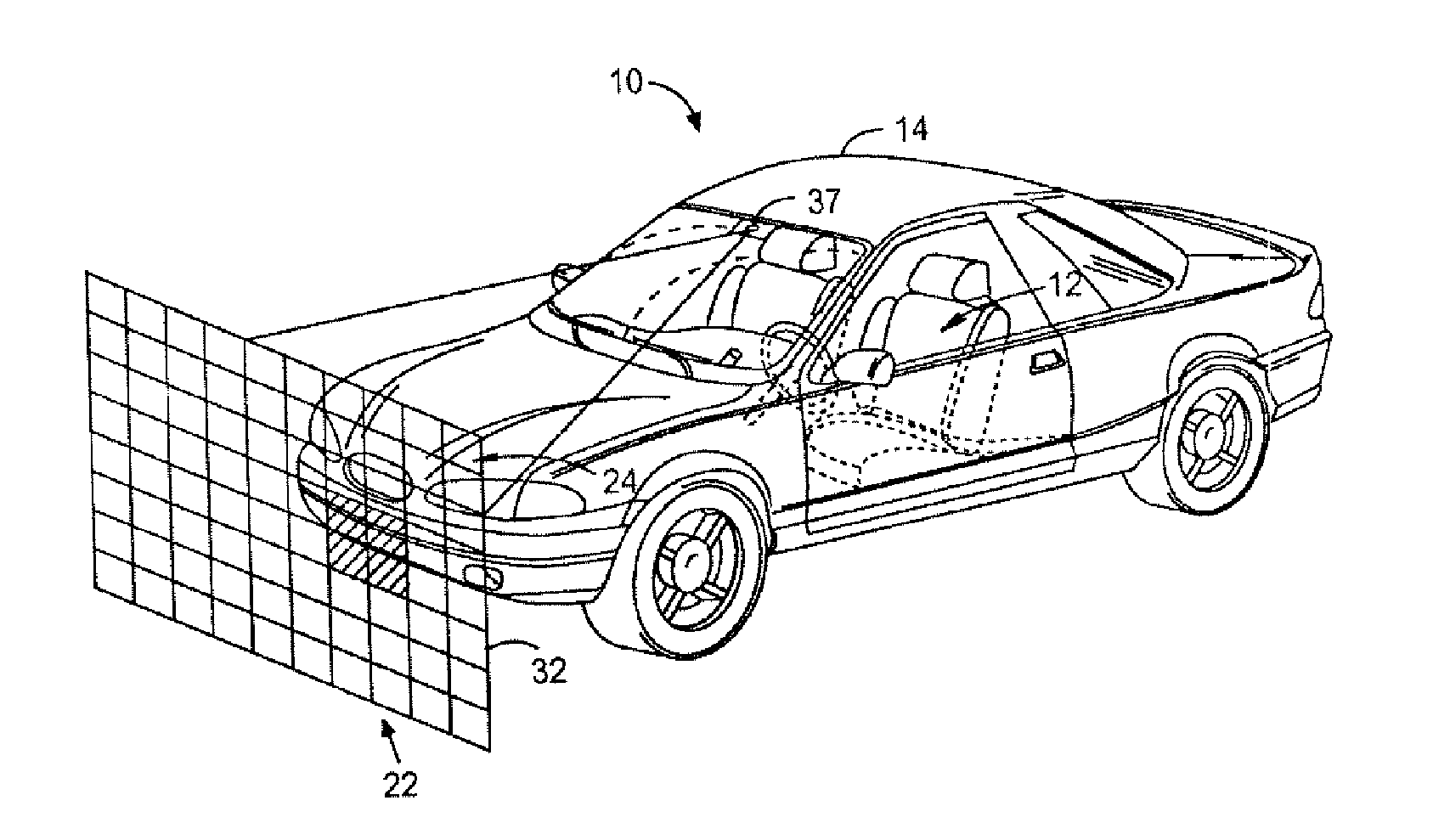
[0025] In the following figures the same reference numerals will be used to refer to the same components. While the present invention is described with respect to a system and method of actively attenuating selected portions of illumination beams of an active night vision system and an active headlamp system, the present invention may be applied in various applications and systems, such as near infrared imaging applications, adaptive cruise control applications, collision avoidance and countermeasure systems, image processing systems, back-up lighting system, and other lighting, imaging, and object detection systems where attenuation of selected portions of an illumination beam is desired. The present invention may be applied in various types and styles of vehicles as well as in non-vehicle applications.

[0026] Also, although the present invention is primarily described with respect an active night vision system illumination source and to headlamps of a vehicle, the present inventio...


PUM


Abstract

An active light source operating system (10,11) for a vehicle (14) includes a light source (50) that generates an initial illumination beam (54). A selective attenuation filter (27,52) forms an emitted illumination beam (56), with an associated light attenuation matrix (32,33), in response to the initial illumination beam (54). A sensor (31) detects an object and generates an object detection signal. A controller (35) is coupled to the selective attenuation filter (27,52) and said sensor (31). The controller (35) attenuates a pixel (104) in the light attenuation matrix (32,33) in response to the object detection signal.

Description

TECHNICAL FIELD [0001] The present invention relates to night vision systems. More particularly, the present invention is related to an active system and method of illuminating selected areas external to a vehicle and illuminating the areas with an appropriate level of illumination. BACKGROUND OF THE INVENTION [0002] Night vision systems allow a vehicle occupant to better see objects during relatively low visible light level conditions, such as at nighttime. Night vision systems typically are classified as either passive night vision systems or active night vision systems. Passive systems simply detect ambient infrared light emitted from the objects within a particular environment. Active systems utilize a near infrared (NIR) light source to illuminate a target area and subsequently detect the NIR light reflected off objects within that area. [0003] Active systems provide improved resolution and image clarity over passive systems. Active systems utilize laser or incandescent light s...

Claims


Application Information

Patent Timeline
Patent Type & Authority Applications(United States)
IPC IPC(8): B60Q1/00F21V21/28
CPCB60Q1/085B60Q2300/056
Inventor SHAFFER, ARIC
Owner FORD GLOBAL TECH LLC
Why Eureka
Try Eureka