PDC drill bit with cutter design optimized with dynamic centerline analysis and having dynamic center line trajectory

a drill bit and cutter technology, applied in the direction of instruments, analogue processes for specific applications, borehole/well accessories, etc., can solve the problems of significant expense involved in the design and manufacture of drill bits and in the drilling of wells, so as to reduce the magnitude of total resultant imbalance forces, improve the accuracy of calculations, and increase the proportion of time

Inactive Publication Date: 2006-07-27
SMITH INT INC
View PDF46 Cites 35 Cited by
  • Summary
  • Abstract
  • Description
  • Claims
  • Application Information

AI Technical Summary

Benefits of technology

[0016] In other aspects of the invention, the modeling method can include selecting a drill bit as a starting model to be simulated, selecting an earth formation to be represented as drilled, and simulating the drill bit drilling the earth formation. The simulation according to these aspects of the invention includes numerically rotating the bit, calculating bit interaction with the earth formation during the rotating, and determining the resultant imbalance forces and the resultant Beta angle between resultant radial and circumferential vector components of imbalanced forces acting at the center of the face of the drill bit during the rotation based on the calculated interaction of the selected drill bit with the selected earth formation. Empirical data for a drill bit and / or for a given earth formation can also be used to modify calculation coefficients to improve the accuracy of the calculations. Modifications to the design are made both to decrease the magnitude of the total resultant imbalance forces and to increase proportion of time that the Beta angle is at or near 180 during. Generally, an increased average Beta angle results from increasing the proportion of drilling time that the Beta angle is at or near 180 degrees (β=180°). It will be recognized that in this analysis the maximum β angle will be 180° because two directly opposed vectors are at 180° to each other, and in all cases where the vectors are not opposed to each other at 180°, the angle between them is less than 180°.
[0017] In other aspects, the invention also provides a method dynamically modeling a drill bit during simulated drilling in an earth formation. “Dynamically modeling” as used in this disclosure means modeling a drill string without an assumed constraint that the centerline of the drill bit is aligned with the centerline of the hole bored into the earth formation. Thus, if the drill bit wobbles or gyrates at the end of a drill string during drilling, the dynamic model accounts for the increased depth of cut for certain cutters and the decreased depth of cut for other cutters. The centerline of the drill bit for dynamically modeling a drill bit is not arbitrarily constrained to align with the centerline of the bore hole. For improved accuracy the centerline of the drill bit is constrained by appropriately modeled physical and dynamic features of the drill string components, including the number of components, size, length, strength, modulus of elasticity of each component and of the connectors between components, contact of the components with the bore hole, impact forces, friction forces, and / or other features that may be associated with a given drill string configuration.
[0018] According to one alternative embodiment of the invention, a method includes generating a visual representation of a fixed cutter bit dynamically drilling in an earth formation, a method for designing a fixed cutter drill bit, and a method for optimizing the design of a fixed cutter drill bit. In another aspect, the invention provides a method for optimizing drilling operation parameters for a fixed cutter drill bit based upon a representation of the drill bit showing the Beta angle (angle) for the drill bit during dynamically simulated drilling rotation in an earth formation and modifying the drill bit design to increase the percentage of time during dynamic drilling that the Beta angle is at β=180°, as large as possible, or as near β=180° as possible.

Problems solved by technology

Significant expense is involved in the design and manufacture of drill bits and in the drilling of well bores.

Method used


Image

  • PDC drill bit with cutter design optimized with dynamic centerline analysis and having dynamic center line trajectory
  • PDC drill bit with cutter design optimized with dynamic centerline analysis and having dynamic center line trajectory
  • PDC drill bit with cutter design optimized with dynamic centerline analysis and having dynamic center line trajectory

Examples


example alternative embodiments

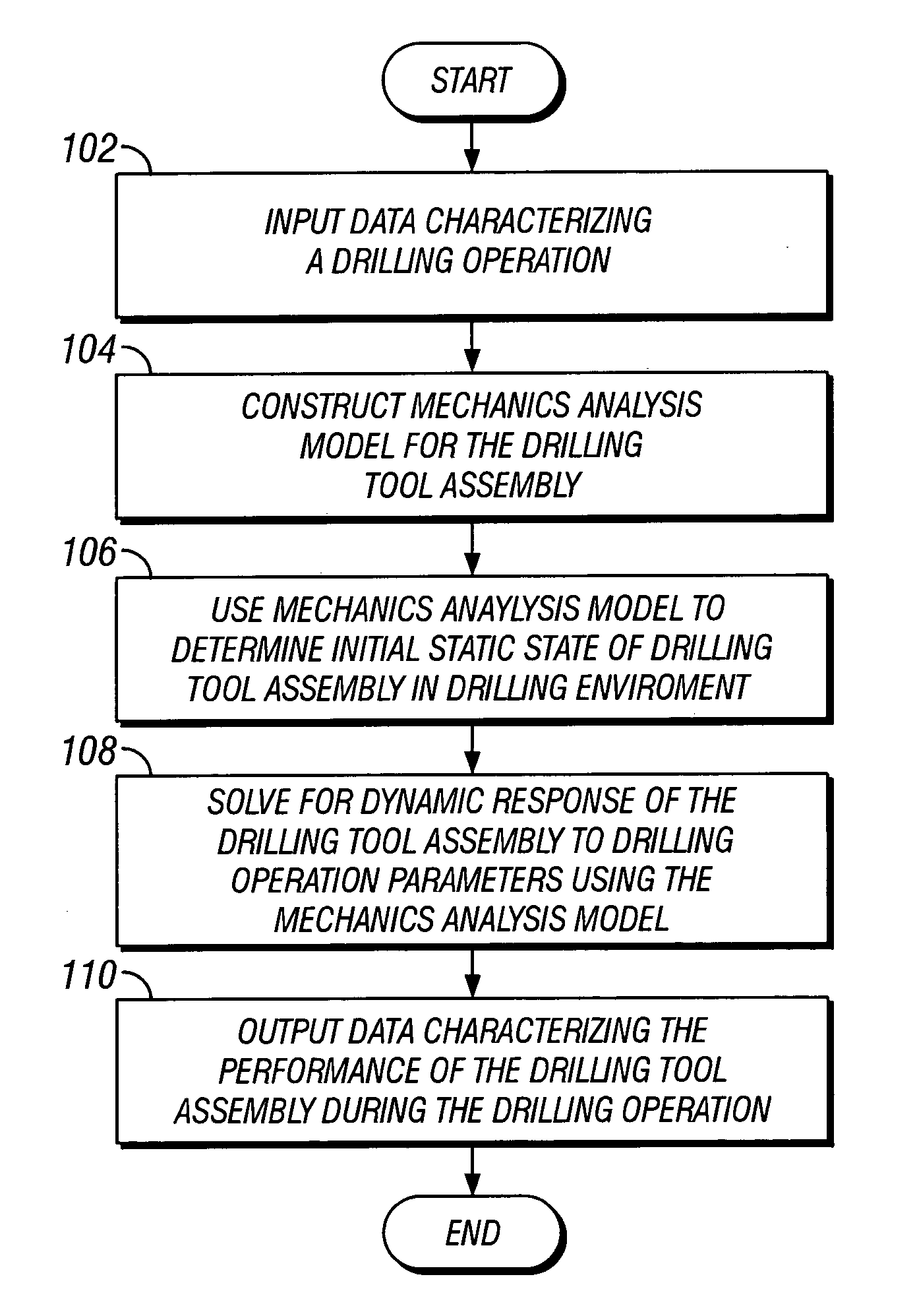
[0218] Those skilled in the art will appreciate that numerous other embodiments of the invention can be devised which do not depart from the scope of the invention as claimed. For example, alternative method can be used to account for dynamic load changes in constraint forces during incremental rotation of a drill string drilling through earth formation. For example, instead of using a finite element method, a finite difference method or a weighted residual method can be used to model the drilling tool assembly. Similarly, embodiments of the invention may be developed using other methods to determining the forces on a drill bit interacting with earth formation or other methods for determining the dynamic response of the drilling tool assembly to the drilling interaction of a bit with earth formation. For example, other method may be used to predict constraint forces on the drilling tool assembly or to determine values of the constraint forces resulting from impact or frictional cont...


PUM


Abstract

A method for designing a fixed cutter drill bit includes simulating the fixed cutter drill bit drilling in an earth formation, determining a dynamic centerline trajectory of the drill bit, and adjusting at least one design parameter based upon the graphical display of at least the dynamic centerline trajectory. To improve performance, the method can include graphically displaying the dynamic centerline trajectory and/or repeating the simulating, determining, displaying and adjusting to change a simulated performance of the fixed cutter drill bit. A drill bit design may be selected and a drill bit may be made according to the design resulting from the method of designing.

Description

CROSS-REFERENCE TO RELATED APPLICATIONS [0001] This is an application for patent and is related to co-pending and co-owned U.S. patent application entitled “Methods For Designing Fixed Cutter Bits and Bits Made Using Such Methods” (Attorney Docket Number 05516.191001) filed on Jul. 9, 2004, U.S. patent application entitled “Methods For Modeling, Displaying, Designing, And Optimizing Fixed Cutter Bits (Attorney Docket Number 05516.192001) filed on Jul. 9, 2004, U.S. patent application entitled “Methods for Modeling Wear of Fixed Cutter Bits and for Designing and Optimizing Fixed Cutter Bits,” (Attorney Docket Number 05516.193001) filed on Jul. 9, 2004, U.S. patent application entitled “Methods For Modeling, Designing, and Optimizing Drilling Tool Assemblies,” (Attorney Docket Number 05516.194001) filed on Jul. 9, 2004, and U.S. patent application entitled “PDC Drill Bit With Cutter Design Optimized With Dynamic Centerline Analysis Having An Angular Separation In Imbalance Forces Of 1...

Claims


Application Information

Patent Timeline
Patent Type & Authority Applications(United States)
IPC IPC(8): G06G7/48
CPCE21B10/00E21B10/42E21B41/0092G06F30/00G06F30/20
Inventor CARIVEAU, PETER THOMASDURAIRAJAN, BALAHUANG, SUJIAN J.
Owner SMITH INT INC
Why Eureka
Try Eureka