Electrostatic suction type jettint device

Active Publication Date: 2006-08-03
KONICA MINOLTA INC +1
View PDF4 Cites 9 Cited by
  • Summary
  • Abstract
  • Description
  • Claims
  • Application Information

AI Technical Summary

Benefits of technology

[0057] The present inventors found that it is possible to decrease the size of the electric field which is conventionally large, and also possible to decrease the amount of movement of the electric charge at the meniscus 22 of a fluid. This can be realized by using a nozzle 23 whose nozzle diameter is shorter toward a fluid-eje

Problems solved by technology

As a result, the droplet may not be able to reach the printing medium separated in a predetermined distance.
Even when the droplet reaches the printing medium, the positioning accuracy of the droplet is low.
However, according to the conventional piezo ink jet head and the conventional thermal ink jet head, the following problems occur when the size of the ejected droplet is decreased, that is, when the ejection energy of the droplet per unit volume is increased.
It was especially difficult to set the amount of the ejected droplet to be equal to or less than 1 pl, that is, difficult to set the diameter of the droplet to be equal to or less than Φ10 μm.
It is difficult to improve the ejection energy, per unit volume, of the ejected droplet.
Pressure generated when bubbles are formed is physically limited.
Therefore, it is difficult to improve the ejection energy, per unit volume, of the ejected droplet of the ink.
Therefore, in the case of ejecting extremely minute droplet, it is very difficult to suppress the variation of the size of the droplet.
Because typical ink contains variou

Method used


Image

  • Electrostatic suction type jettint device
  • Electrostatic suction type jettint device
  • Electrostatic suction type jettint device

Examples


Example

[0165] The following description explains the best mode (hereinafter referred to as “embodiment”) for carrying out the present invention. Note that, the present embodiment explains an electrostatic attraction ink jet device which uses ink as a fluid.

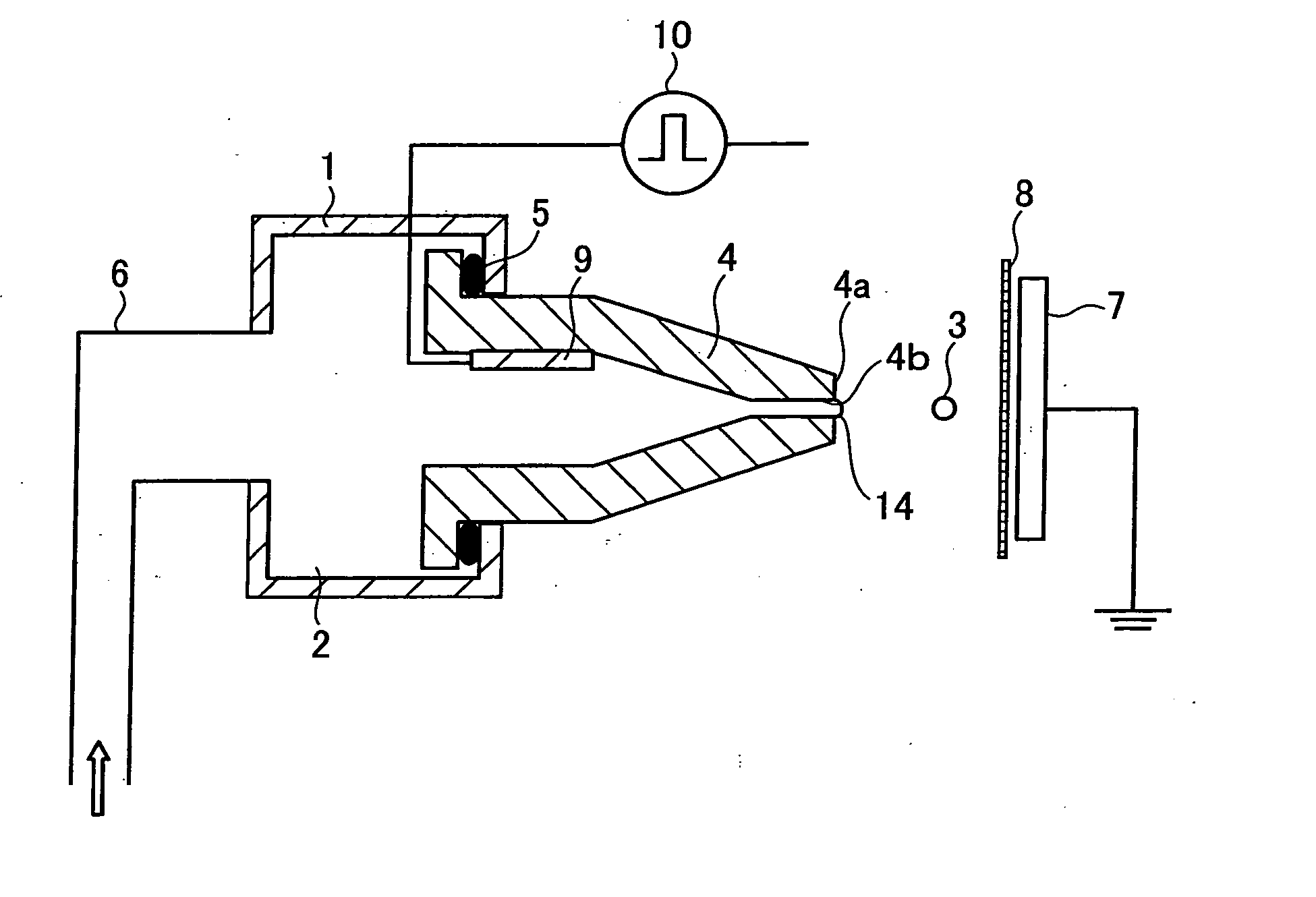
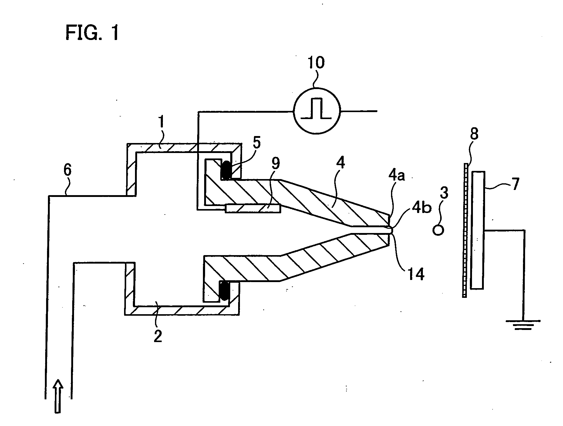
[0166]FIG. 1 is a diagram illustrating an arrangement of an ink jet device according to the present embodiment.

[0167] As illustrated in FIG. 1, the ink jet device includes a nozzle 4 for ejecting ink 2 which is stored as a fluid in an ink chamber 1. The nozzle 4 is connected with the ink chamber 1 via gaskets 5. In this way, a joint portion between the nozzle 4 and the ink chamber 1 is sealed so that the ink 2 in the ink chamber 1 does not leak to the outside.

[0168] Moreover, an internal diameter of the nozzle 4 becomes shorter toward a tip portion 4a which is on the opposite side of the joint portion between the ink chamber 1 and the nozzle 4, that is, the side from which the ink is ejected. An internal diameter (diameter) of an ink-...


PUM


Abstract

An electrostatic attraction fluid jet device of the present invention is so arranged that a nozzle (4) is formed so as to correspond to a meniscus equivalent to a tip portion in the form of a taylor cone formed in a process of an electrostatic attraction of ink (2) as a conventional fluid. A diameter of an ink-ejecting hole (4b) of the nozzle (4) is set to be substantially the same as a diameter of the tip portion, which is about to be ejected, of the meniscus (14) of ink. Moreover, the diameter of the ink-ejecting hole (4b) of the nozzle (4) is set to be equal to or less than a droplet diameter of the ink (2) which has just been ejected. Therefore, it is possible to provide an electrostatic attraction fluid jet device which can realize a recording device which has high resolution, is safe and is highly versatile.

Description

TECHNICAL FIELD [0001] The present invention relates to an electrostatic attraction fluid jet device which ejects a fluid, such as ink, onto a target by electrostatically attracting the fluid by electrifying the fluid. BACKGROUND ART [0002] Generally, there exist various fluid jet methods by which a fluid, such as ink, is ejected onto a target (printing medium). Here, the following description explains an ink jet printing method in which the ink is used as the fluid. [0003] As drop on demand ink jet printing methods, (i) a piezo printing method in which a piezoelectric phenomenon is utilized, (ii) a thermal printing method in which a film boiling phenomenon of ink is utilized, and (iii) an electrostatic attraction printing method in which an electrostatic phenomenon is utilized, etc are developed. Especially, in recent years, a high-resolution ink jet printing method is strongly demanded. In order to realize the high-resolution ink jet recording, it is indispensable to reduce the si...

Claims


Application Information

Patent Timeline
IPC IPC(8): B41J2/41G11B3/00B41J2/06
CPCB41J2/06B41J2002/14475B41J2/14B41J2/1433
Inventor HIGUCHI, KAORUNISHI, YASUOMURATA, KAZUHIROYOKOYAMA, HIROSHI
Owner KONICA MINOLTA INC
Why Eureka
Try Eureka