Clamp

Inactive Publication Date: 2005-02-10
D & D GROUP PTY LTD
View PDF12 Cites 8 Cited by
  • Summary
  • Abstract
  • Description
  • Claims
  • Application Information

AI Technical Summary

Benefits of technology

[0010] said screw means being adapted in use to cooperate with said teeth on said band such that when said screw means is rotated in a first direction, said loop is decreased in size to clamp around a said article.
[0011] The band may include a section extending from the proximal end of the head which is of an arcuate configuration longitudinally of the band so as to enable it to more easi

Problems solved by technology

Whilst these clamps generally function efficiently, they are not suited to being manufactured from plastics.
Further, as a number of steps are required in their construction such as joining of the housing to the strap, the cost of manufacture of clamps of this type can be high.
A disadvantage of the above clamps is that the housing in use is held against the periphery of the article being gripped however because the housing is often of planar form on its side adjacent the article, it will not lie flush with a curved surface around which the strap is looped.
This can make tightening of the strap difficult and further when tightening occurs, the full circumference of the curved surface is not closely gripped because of the planar surface of the housing is in contact with the curved surface of the article.
As however, the housing forms part of the strap and is coextensive with the strap, tightening of the strap about the article will apply a radially inwardly directed force tending to caus

Method used


Image

  • Clamp
  • Clamp
  • Clamp

Examples


Example

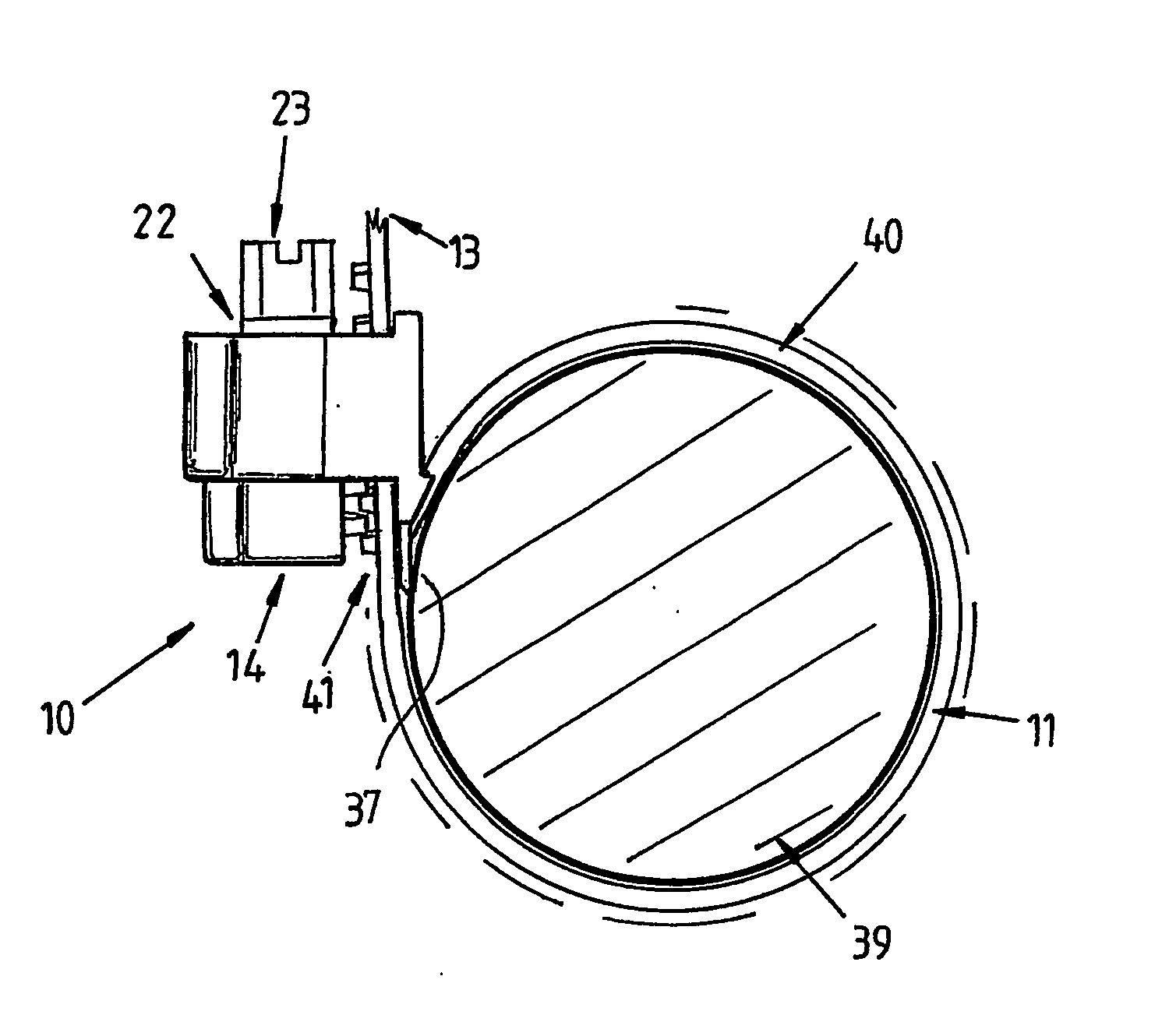
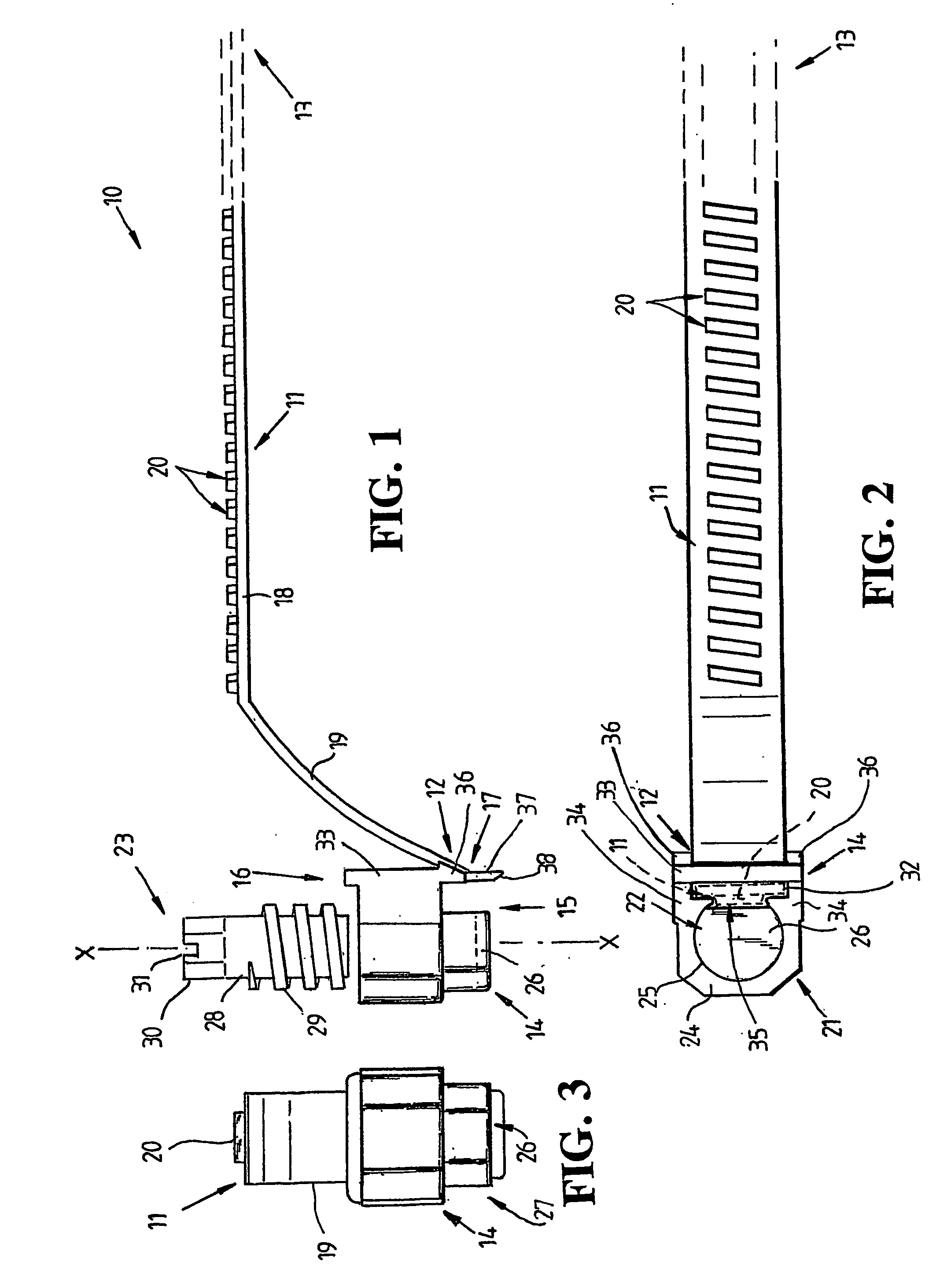
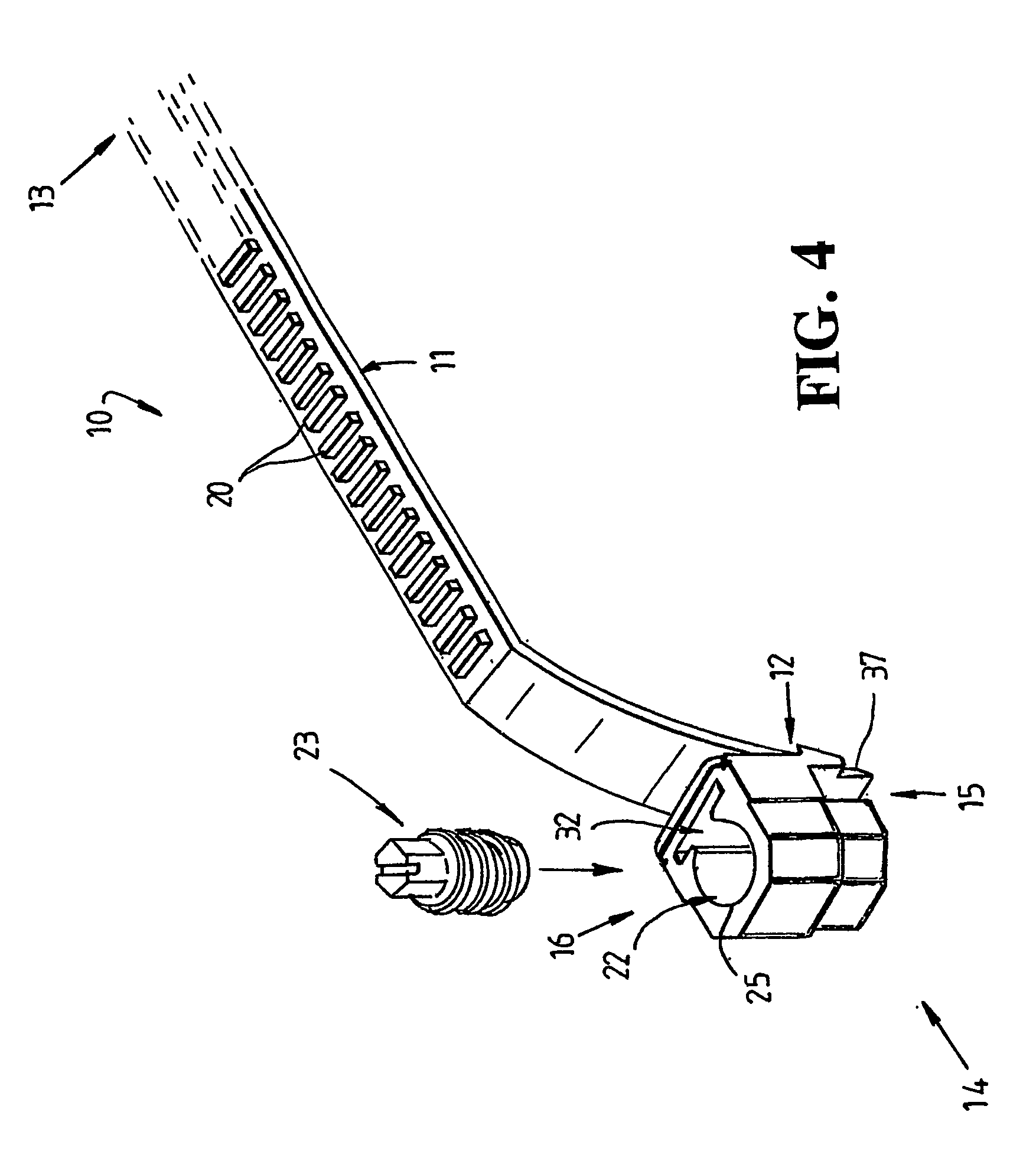
[0030] Referring to the drawings and firstly to FIGS. 1 to 4, there is illustrated a clamp 10 and components thereof according to an embodiment of the present invention. The clamp 10 may commonly be used as a hose or pipe clamp or for clamping cables or other like articles but it may be used to loop about and clamp any article or articles of any cross section. The clamp 10 comprises an elongated flexible band 11 having a proximal end 12 and a distal end 13 and an integrally formed screw supporting head 14 at the proximal end 12 of the band 11. The band 11 may as indicated by the dotted outline FIG. 1 be of any length. The head 14 has a proximal end 15 and a distal end 16 and as shown in FIG. 1, the proximal end 12 of the band 11 is only joined to the head 14 adjacent its distal end 15 at 17. The remainder of the head 14 is free of the band 11 such that the distal end 16 of head 14 is spaced from the band 11.

[0031] The band 11 includes a generally strip-like main body 18 of flat rec...


PUM


Abstract

An article clamp (10) of the band type including an elongated flexible band (11) having on one side a plurality of spaced teeth (20) and a head (14) having a chamber (22) for receiving screw (23) for cooperation with the teeth (20) on the band (11), a proximal end (12) of the band (11) being connected to the proximal end (15) only of the head (14) such that the distal end (16) of the head (14) is spaced from and free of the band (11), the head (14) further having a passage (30) therethrough for receiving a distal end (13) of the band (11) to form the band (11) into a loop.

Description

TECHNICAL FIELD [0001] This invention relates to a clamp and more particularly to clamp of the type in which a band is looped around an article to be gripped such as a hose or pipe and tightened to clamp about the article. BACKGROUND ART [0002] A number of different designs and types of hose or pipe clamps are currently available. Generally, the known hose or pipe clamps include a metal strap which is fixed at one end to a separate metal housing, the housing defining a recess which has its longitudinal axis aligned with the axis of the strap. A worm screw is captured within the housing recess and cooperates with an end of the strap which is looped about an article to be gripped. For this purpose, the strap is provided with spaced recesses or slots for cooperation with the threads on the worm screw such that when the worm screw is rotated in opposite directions the metal strap loop is tightened to grip the article or loosened to free the article. The housing is attached to the one en...

Claims


Application Information

Patent Timeline
IPC IPC(8): F16B2/08F16L33/08
CPCF16L33/08Y10T24/14Y10T24/1498Y10T24/1441Y10T24/1427Y10T24/1406Y10T24/141
Inventor CASTELLANOS, PETER
Owner D & D GROUP PTY LTD
Why Eureka
Try Eureka