Vehicle body front part structure

Inactive Publication Date: 2011-09-01
SUZUKI MOTOR CO LTD
View PDF10 Cites 10 Cited by
  • Summary
  • Abstract
  • Description
  • Claims
  • Application Information

AI Technical Summary

Benefits of technology

[0019]In the first or second aspect of the present invention, if an engine mount interposed between an engine and the apron side member is connected to the apron side member, and the tray body part is fixed to the apron side panel with a fixing member, and the tray body part is placed on and fixed to the engine mount, the effects described below can be achieved.
[0020]Since the tray body part is fixed to the apron side panel with the fixing member, and the tray body part is placed on and fixed to the engine mount, the tray can be supported stably, and a burden imposed on the leg part can be eased, so that the leg part can be decreased in size. Also, the battery placed in the tray body part plays a role of a weight on the engine mount, so that vibrations of the engine mount can be restrained.
[0021]In the present invention, if a support part for supporting an accessory of an engine is provided in the tray body part, a space in the engine compartment can be utilized effectively.
[0022]In the present invention, if the support part is formed by a verti

Problems solved by technology

Unfortunately, according to the above-described conventional structure, the sealer has been unable to be applied to a joint portion located on the outside in the vehicle width direction of the t

Method used


Image

  • Vehicle body front part structure
  • Vehicle body front part structure
  • Vehicle body front part structure

Examples


Embodiment Construction

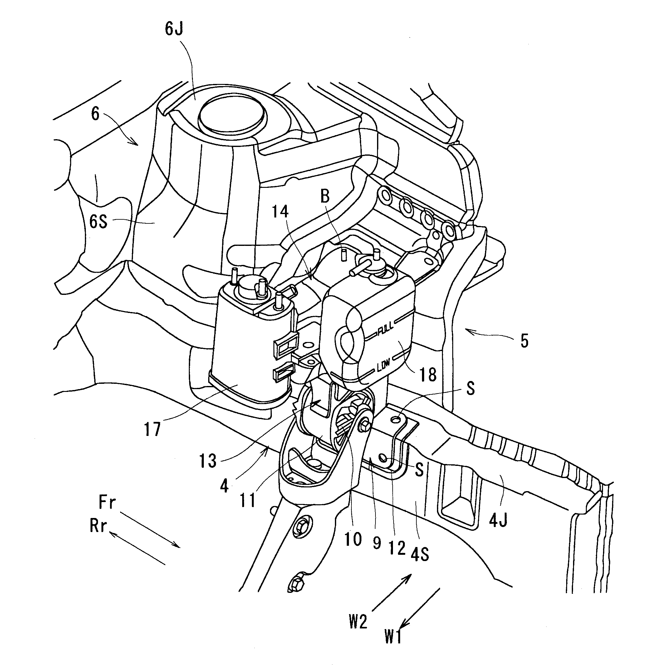
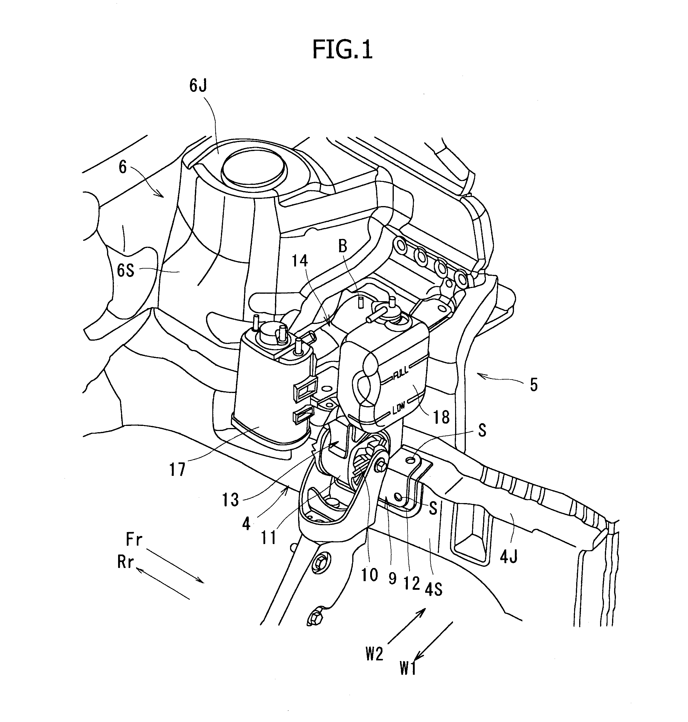
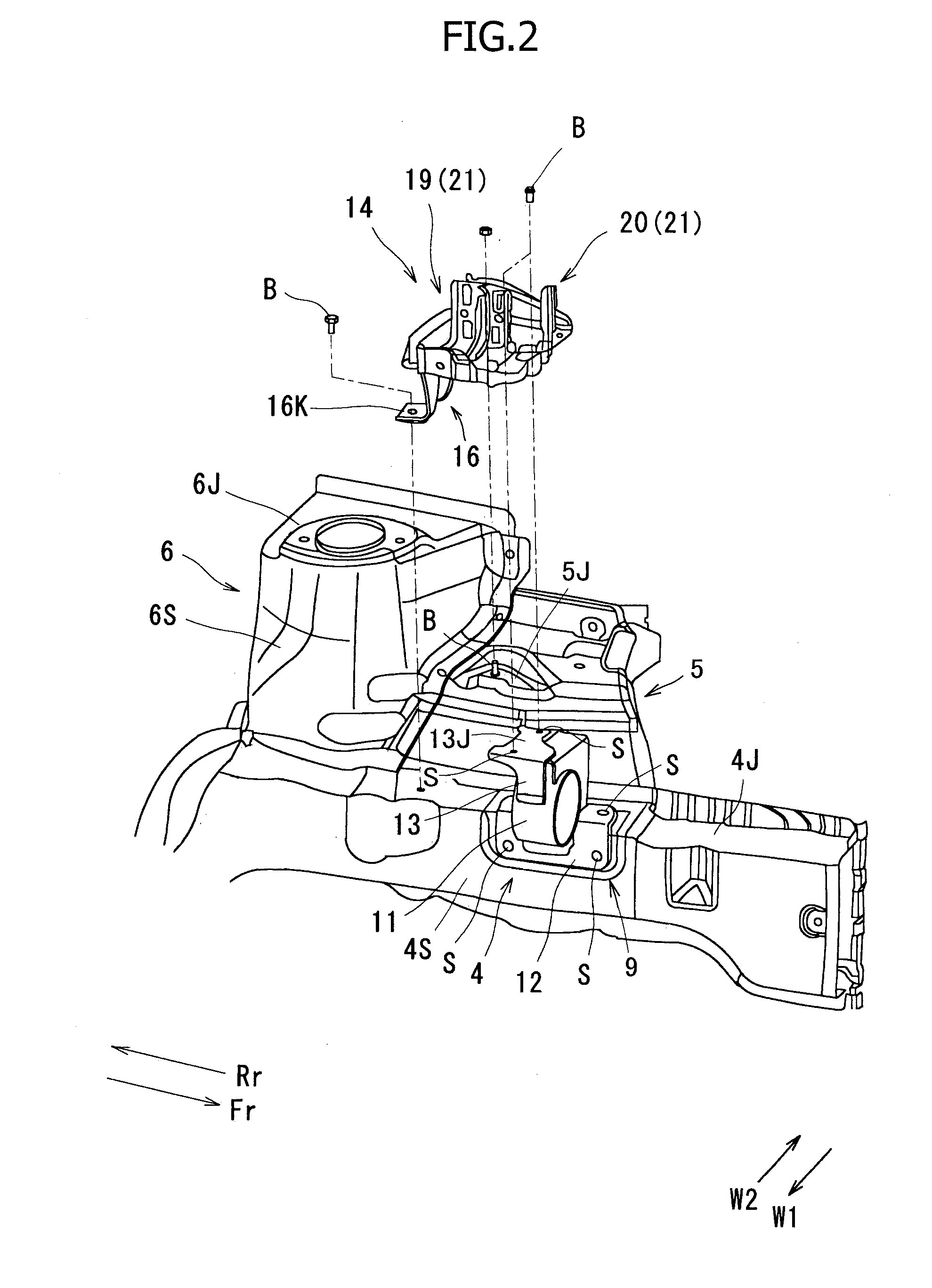
[0033]FIG. 1 and FIGS. 3(a) and 3(b) show a vehicle body front part structure of a motor vehicle. This vehicle body front part structure includes a dash panel 3 partitioning a vehicle compartment 2 from an engine compartment 1, an apron side member 4 of a rectangular tubular shape extending in the vehicle longitudinal direction, an apron side panel 5, and a strut tower part 6 expanding from the apron side panel 5 into the engine compartment 1 on the inside W1 in the vehicle width direction.

[0034]The strut tower part 6 includes a peripheral wall 6S having a trapezoidal transverse cross section narrowing toward the inside W1 in the vehicle width direction, and an upper wall 6J connected to the upper end portion of the peripheral wall 6S, and incorporates a suspension strut for a front wheel. The corner portion of the peripheral wall 6S in the transverse cross section is curved in an arc shape. The apron side panel 5 is joined by welding to the apron side member 4, and a part thereof p...


PUM


Abstract

A vehicle body front part structure has an apron side panel 5 joined to an apron side member 4 extending along the vehicle longitudinal direction, and a tray 14 for battery supported on the apron side member 4. In the front part structure, a leg part 16 is provided in an tray body part 15, a lower end part 16K of the leg part 16 is fixed to the apron side member 4 with a fixing member B, and the leg part 16 is formed of a plate material so that the deformation of the apron side member 4 is allowed when a vehicle longitudinal force is applied to the apron side member 4.

Description

CROSS-REFERENCE TO RELATED APPLICATIONS[0001]The present application claims the benefit of Japanese Patent Application No. 2010-041798, filed Feb. 26, 2010. The entire disclosure of the above-identified application is incorporated by reference herein.FIELD OF THE INVENTION[0002]The present invention relates to a vehicle body front part structure in which an apron side panel is connected to an apron side member extending along the vehicle longitudinal direction, and a tray for a battery is supported at the apron side member.BACKGROUND OF THE INVENTION[0003]Conventionally, in the vehicle body front part structure, as shown in FIG. 9, a pair of front and rear tray support stands 30 have been weldedly fixed to an apron side member 4 on the vehicle front side Fr of a strut tower part 6, and a tray 14 has been placed on the tray support stands 30 and fixed thereto by bolts B.[0004]The tray support stand 30 is formed, as viewed from the side (viewed in the vehicle width direction), into a ...

Claims


Application Information

Patent Timeline
IPC IPC(8): B62D21/15
CPCB60R16/04B60R16/0238
Inventor SOGABE, MICHIHIRO
Owner SUZUKI MOTOR CO LTD
Why Eureka
Try Eureka