Server and communication terminal

a server and terminal technology, applied in the field of communication techniques using cellular communication functions, can solve problems such as security risks and inability of the server to interpret the format of application data

Active Publication Date: 2014-06-26
PANASONIC INTELLECTUAL PROPERTY CORP OF AMERICA
View PDF8 Cites 37 Cited by
  • Summary
  • Abstract
  • Description
  • Claims
  • Application Information

AI Technical Summary

Benefits of technology

[0015]According to one aspect of the present disclosure, for example, the effect of being able to include the IP address of a UE in a trigger response as a control message and report it to an SCS before the start of communication with the SCS can be realized.

Problems solved by technology

Therefore, the SCS that received the IP packet including the application data from the UE after transmitting the control message cannot identify the source UE because the SCS does not have information on the IP address set in the source address of an IP header.
Even when an identifier of the UE is included in the application data within the IP packet, since the application data is created in a format interpreted by the AS, the SCS cannot interpret the format of the application data.
Thus, since the SCS cannot authenticate the source UE when receiving the IP packet, the SCS passes the data to the AS without identifying the UE as the source of the IP packet, causing a security risk.

Method used


Image

  • Server and communication terminal
  • Server and communication terminal
  • Server and communication terminal

Examples


first embodiment

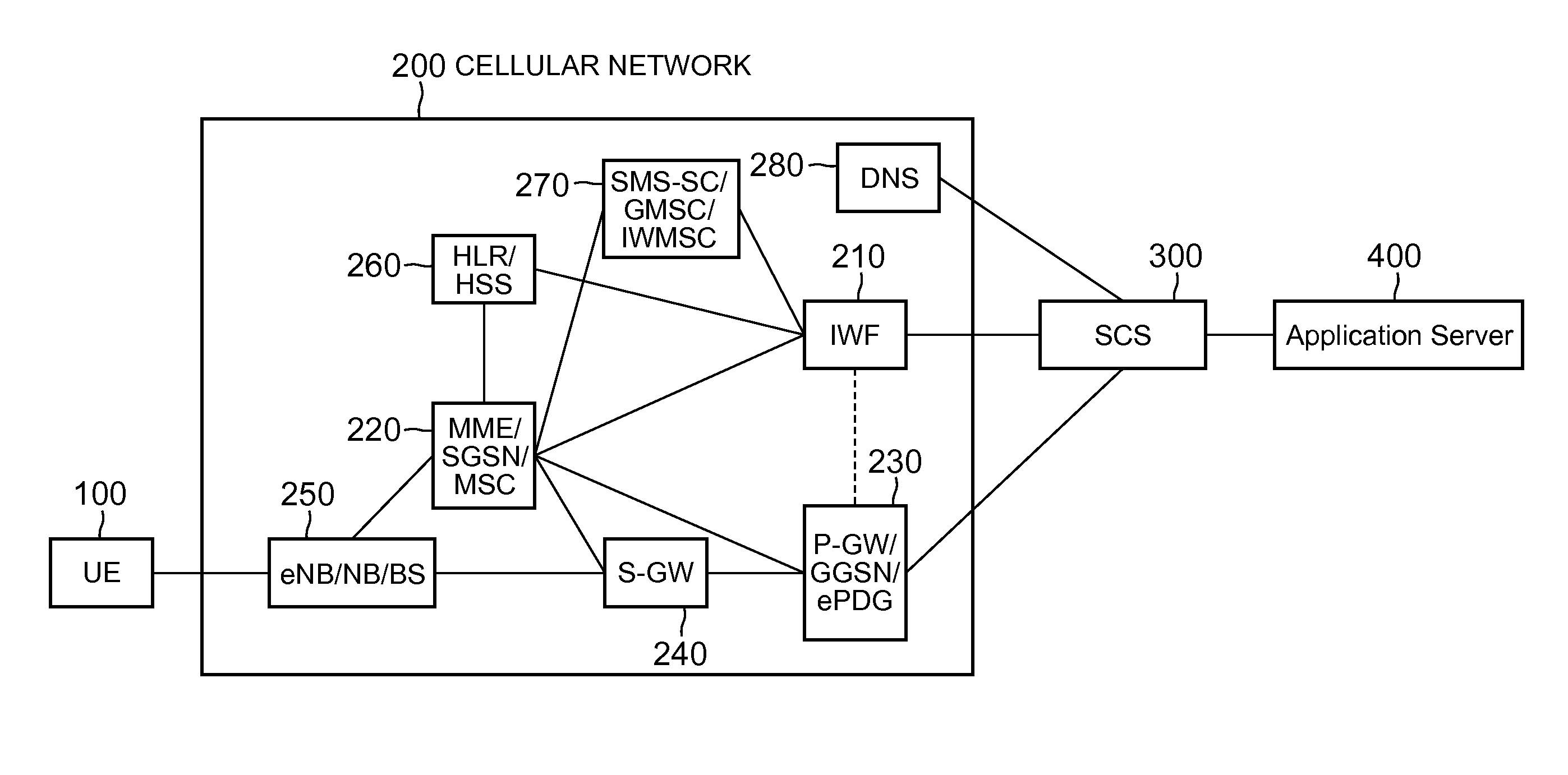
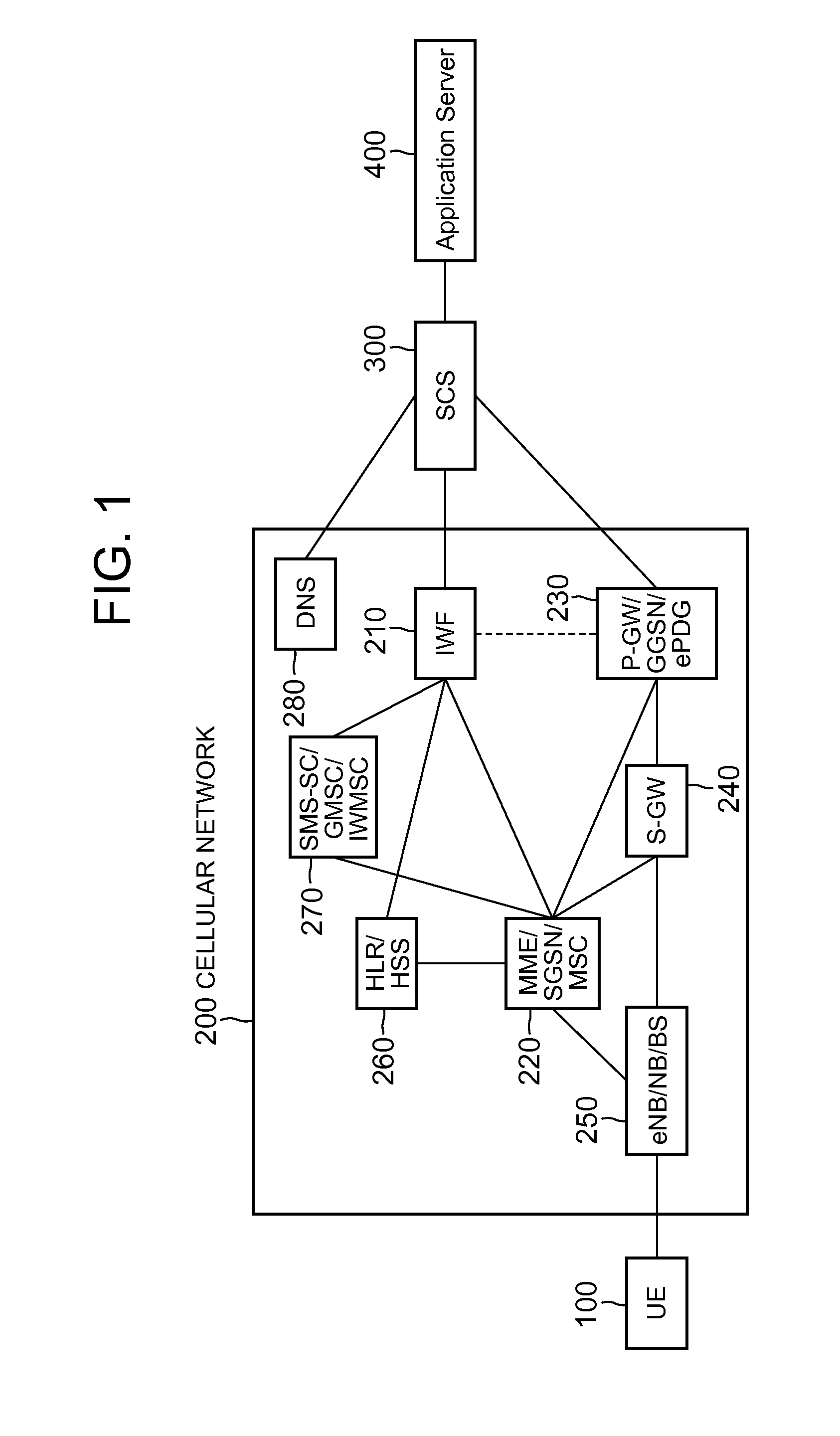
[0029]First, the first embodiment of the present disclosure will be described. FIG. 1 is a diagram showing an example of a network configuration in the first embodiment of the present disclosure. Illustrated in FIG. 1 are a UE 100 as a cellular communication terminal, a cellular network (called a core network or a 3GPP network as well, which may be simply referred to as a network below) 200 to which the UE 100 attaches, an SCS 300 for transmitting a trigger request addressed to the UE 100, and an application server 400 for performing data communication with the UE 100.

[0030]Also illustrated in FIG. 1 as components of the cellular network 200 are an IWF 210 for connecting the cellular network 200 with the SCS 300, an MME / SGSN / MSC (Mobility Management Entity / Serving GPRS Support Node / Mobile Switching Center) 220 for performing the management of position information (location) on the UE 100 and communication control of the UE 100 (line switch control or packet exchange control), a P-GW...

second embodiment

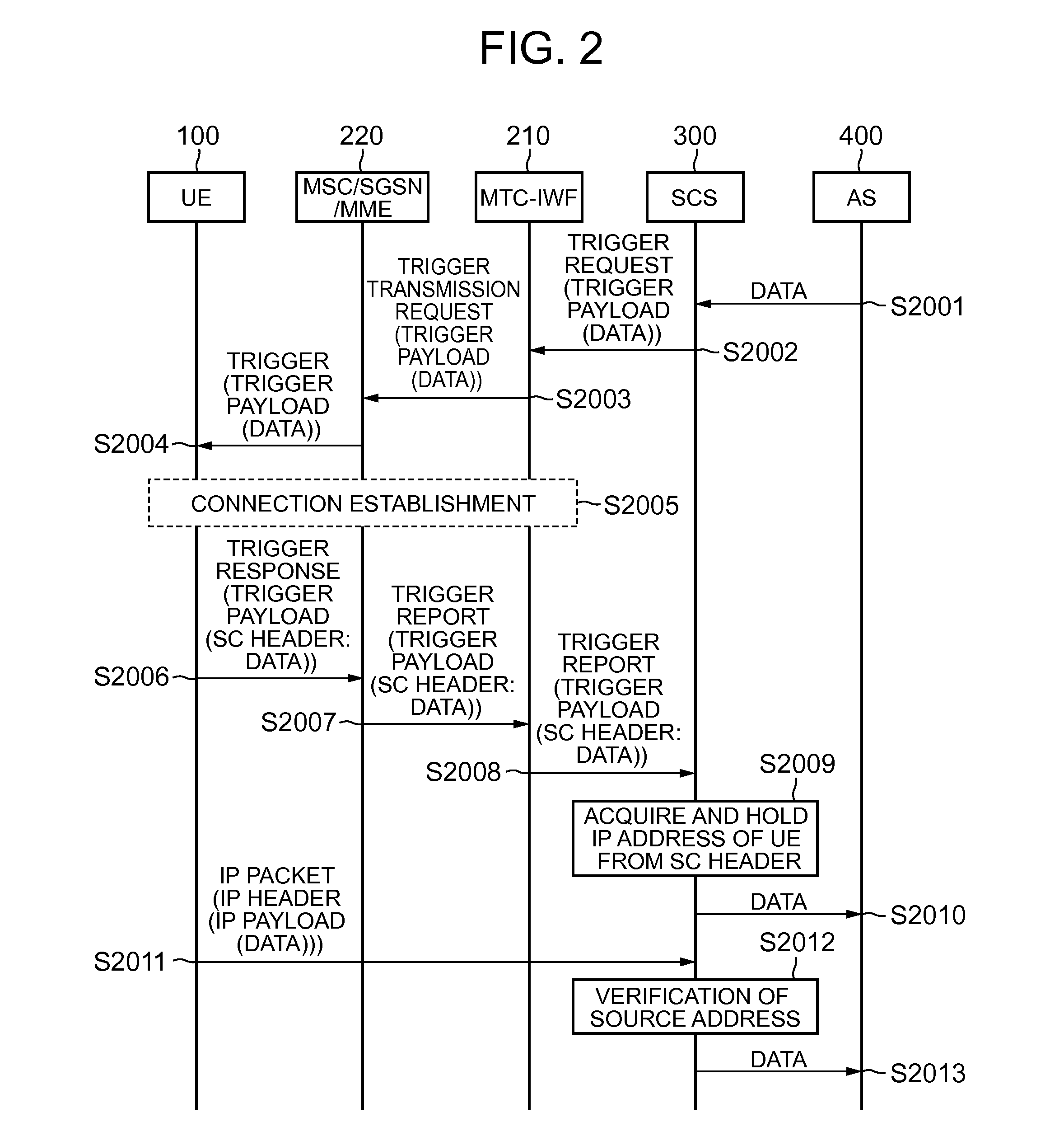
[0066]Next, a method of reporting an IP address to the SCS based on application data included in the application payload of the device trigger in the second embodiment of the present disclosure will be described.

[0067]FIG. 10 is a sequence chart showing a first example of operation of the SCS 300 and the UE 100 in the second embodiment of the present disclosure. A difference from the first example in the first embodiment of the present disclosure described with reference to FIG. 2 is that the UE 100 that received the trigger confirms application data received in step S10005. Since the other steps are the same as those in FIG. 2, redundant description will be omitted. FIG. 11 is a flowchart showing the first example of processing (steps S10004 to S10007) performed by the UE 100 that received the device trigger. A difference from the operation of the UE 100 in the first embodiment of the present disclosure described with reference to FIG. 3 is that it is confirmed in step S11003 wheth...


PUM


Abstract

Disclosed is a technique for reporting the IP address of a UE using a response message to a device trigger. A control message receiving unit receives, from a network, a control message generated based on a trigger request message transmitted from the predetermined communication device for requesting the transmission of the control message to a communication terminal. A determining unit determines whether to perform communication with the predetermined communication device using an IP packet. A connection management unit acquires an IP address allocated to an IP connection used in communication with the predetermined communication device when determining to perform the communication using the IP packet at the time of receiving the control message at the control message receiving unit. A response message transmitting unit transmits a response message to the control message to the network, where the response message includes the IP address acquired by the connection management unit.

Description

TECHNICAL FIELD[0001]The present disclosure relates to a communication technique using a cellular communication function, and particularly to a server and a communication terminal for performing communication using a technique for communication between machines (called Machine to Machine Communication or Machine Type Communication, which is referred to as M2M communication or MTC) below)).BACKGROUND ART[0002]The cellular communication function is not only used in voice communication and data communication between cellular phones and smartphones, but also widely used in devices for M2M communication (also called MTC devices). The number of cellular communication terminals (hereinafter referred to as UEs (User Equipment) or communication terminals) including MTC devices will continue to increase in the future.[0003]When a user and an application (hereinafter also called an MTC application, an application server, or an AS (Application Server)) operated by the user transmit application ...

Claims


Application Information

Patent Timeline
Patent Type & Authority Applications(United States)
IPC IPC(8): H04W12/08H04L29/06H04W76/02H04W4/70
CPCH04W4/70H04W76/11H04W12/08H04L63/126
Inventor ASO, KEIGOVELEV, GENADI
Owner PANASONIC INTELLECTUAL PROPERTY CORP OF AMERICA
Why Eureka
Try Eureka