Lens with reference mounting surface

Active Publication Date: 2006-11-16
FUJI PHOTO OPTICAL CO LTD
View PDF2 Cites 2 Cited by
  • Summary
  • Abstract
  • Description
  • Claims
  • Application Information

AI Technical Summary

Benefits of technology

[0007] An objective of the present invention is to provide a lens having a reference mounting surface such that the positioning of the lens becomes insensitive to alignment errors, thereby enabling a sufficient optical performance of the lens to be achieved by using a simple positioning operation when mounting the lens in an optical coupler. In

Problems solved by technology

However, there is a problem in that a ball lens does not efficiently condense light due to the spherical aberration of such a lens being large.
With a lens having a fixed optical axis such as with an aspherical lens, it is generally difficult to obtain a desired optical p

Method used


Image

  • Lens with reference mounting surface
  • Lens with reference mounting surface

Examples


embodiment 1

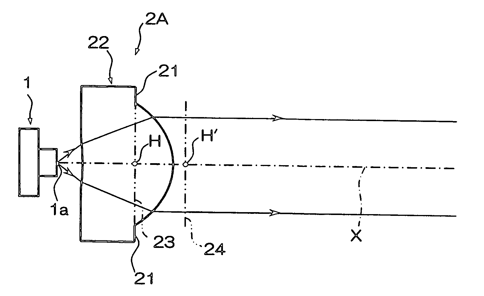
[0017]FIG. 1 schematically shows the construction of a lens having a reference mounting surface according to Embodiment 1 of the present invention. The lens having a reference mounting surface (hereafter referred to as “lens 2A”) is shown in FIG. 1 as being a single lens arranged in the optical coupler of an optical communications system. The lens is constructed so as to collimate divergent light rays emitted from a light emitting point 1a of a light source device 1. The light source device 1 may be a semiconductor laser (LD) or a light-emitting diode (LED).

[0018] As illustrated, within a luminous flux passage region of the lens 2A, the surfaces of the lens are formed as a meniscus lens with its convex surface on the outgoing light side. A flange 22 having a reference mounting surface 21 for abutting to a surface (not shown) of a lens support member at the time of mounting the lens is provided. The reference mounting surface 21 is arranged in a position between a plane 23 that is n...

embodiment 2

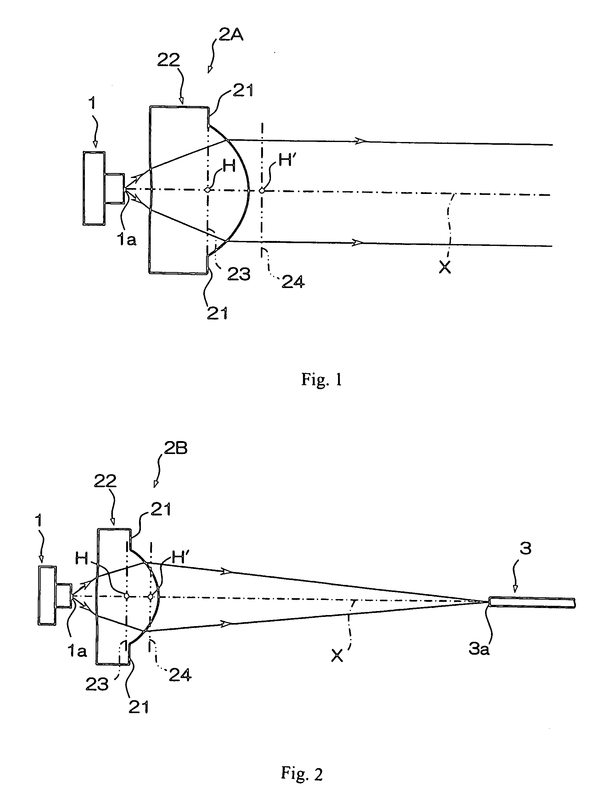
[0022]FIG. 2 schematically shows the construction of a lens with a reference mounting surface according to Embodiment 2 of the present invention. In this embodiment, identical components that are shared with the first embodiment are shown in FIG. 2 using the same numbers as used in FIG. 1.

[0023] A lens with a reference mounting surface (hereinafter referred to as “lens 2B”) shown in FIG. 2 is a single lens arranged between the light source device 1 and an optical fiber 3 on the light receiving side of the optical coupler in an optical communications system, and is constructed such that a divergent light emitted from a light emitting point 1a of the light source device 1 is collected and is incident on an incident light surface 3a of the optical fiber 3.

[0024] As illustrated, the lens 2B is a biconvex lens having surfaces of different curvature, with the numerical aperture (NA) in the luminous flux passage region of the lens surface on the incident light side being greater than tha...


PUM


Abstract

A lens is equipped with a reference mounting surface that is abutted to a surface of a lens support member at the time of mounting the lens, wherein the reference mounting surface is arranged between a plane which is normal to the optical axis of the lens and includes a principal point on the incident light side of the lens and a plane which is normal to the optical axis of the lens and includes a principal point on the outgoing light side of the lens.

Description

TECHNICAL FIELD [0001] The present invention relates to a lens equipped with a reference mounting surface for alignment of the lens; particularly, with the reference mounting surface being suitable for attachment to a support surface of an optical coupler in an optical communications system. BACKGROUND OF THE INVENTION [0002] In an optical communications system that uses one or more optical fibers, wherein an optical coupler having a light sending side and a light receiving side is used, there has been a need for an optical coupling system wherein a divergent light beam that is emitted from the light sending side of the optical coupler is collected and formed into a convergent light beam that is then incident onto an end surface of an optical fiber on the light receiving side of the optical coupler. [0003] Conventionally, a so-called ball lens (i.e., a spherical lens) has been used as a lens in such an optical coupling system to collect the light and to form the light into a converg...

Claims


Application Information

Patent Timeline
IPC IPC(8): G02B7/02
CPCG02B6/4206G02B7/022G02B6/423
Inventor KATSUMA, TOSHIAKIMORI, MASAOKITAHARA, YUOOMURA, MAKOTOYAMAMOTO, YOKO
Owner FUJI PHOTO OPTICAL CO LTD
Why Eureka
Try Eureka