Multimode optical fiber

Inactive Publication Date: 2006-11-23
SUMITOMO ELECTRIC IND LTD
View PDF1 Cites 21 Cited by
  • Summary
  • Abstract
  • Description
  • Claims
  • Application Information

AI Technical Summary

Benefits of technology

[0023] In the multimode optical fiber of the present invention, since the core part has a structure including a plurality of concentric layers in which a refractive index changes stepwise respectively for the layers so as to be higher toward a central area, the refractive index profile does not need to be highly accurately and continuously changed, a production is easy and the refractive index profil

Problems solved by technology

In such a measurement of temperature, when the optical fiber including germanium in a core to adjust a refractive index is used, since attenuation is increased by hydrogen in the submarine resources, a highly accurate measurement cannot be carried out.
The difference in increase of the attenuation causes the temperature detecting accuracy of the DTS to be deteriorated.
However, in this optical fiber, under an environment of

Method used


Image

  • Multimode optical fiber
  • Multimode optical fiber
  • Multimode optical fiber

Examples


example 1

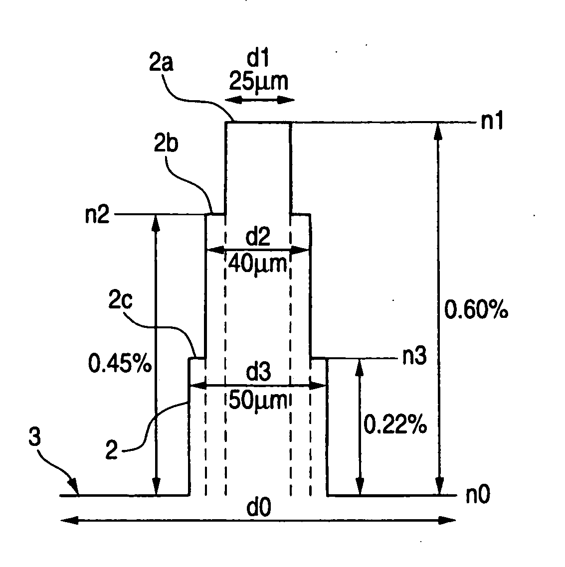
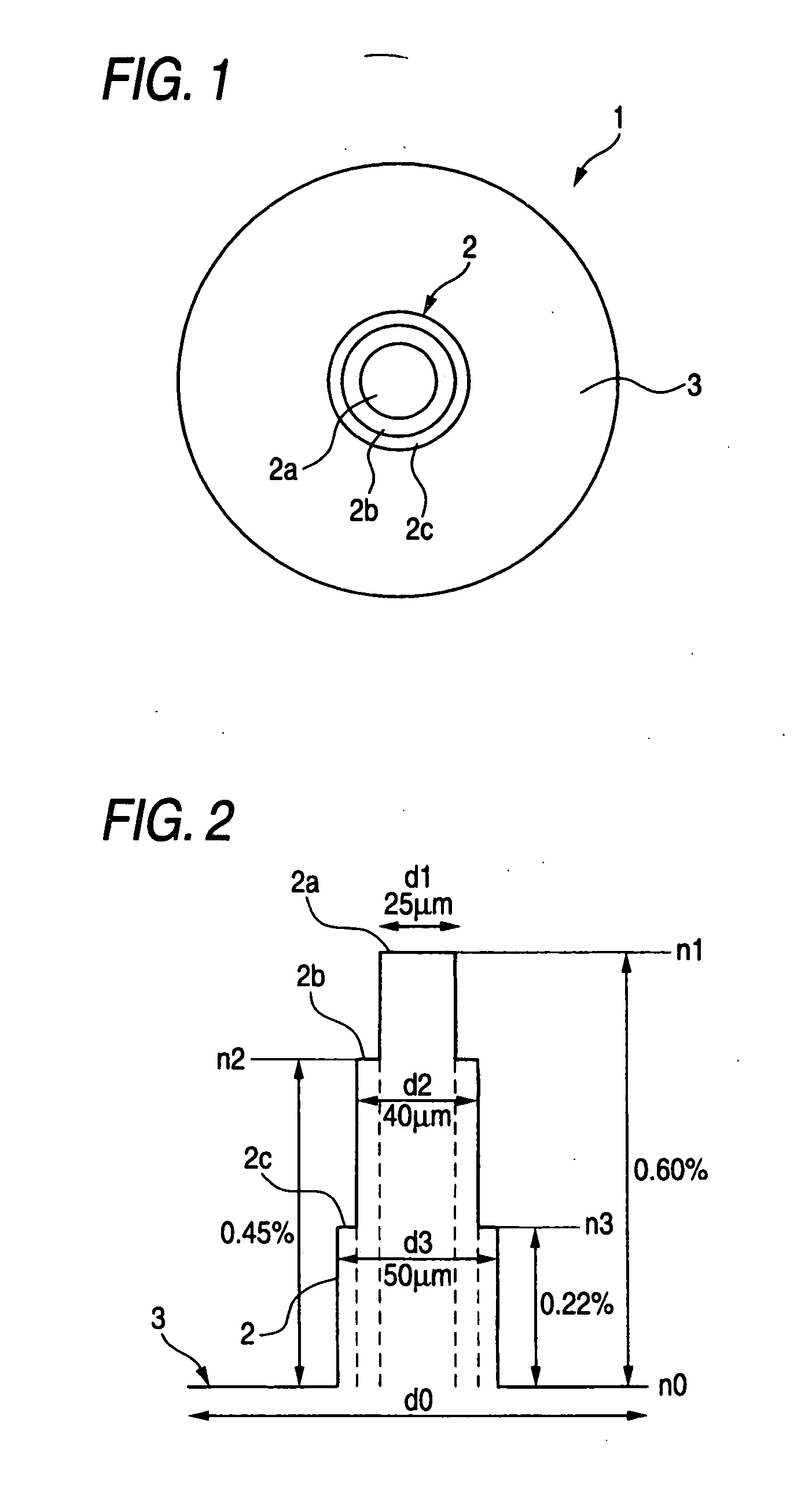
[0083] The refractive index profile of the core part of an optical fiber of an example 1 shows that of a three-step type (the number M of layers of the core part=3) as shown in FIG. 7 and a diameter of the core part is 50 μm. A first core layer has a relative refractive index difference Δn1=0.60% relative to a cladding part and a diameter d1=25 μm. A second core layer has a relative refractive index difference Δn2=0.45% relative to the cladding part and a diameter d2=40 μm. A third core layer has a relative refractive index difference Δn3=0.22% relative to the cladding part and a diameter d3=50 μm. Herein, the relative refractive index difference relative to the cladding part is a ratio of the refractive index difference between the refractive indexes of each of the core layers and the cladding part with respect to the refractive index of the cladding part. In other words, the relative refractive index difference relative to the cladding part is calculated by dividing the refractive...

example 2

[0086] The refractive index profile of the core part of an optical fiber of an example 2 shows that of a three-step type (the number M of layers of the core part=3) as shown in FIG. 8 and a diameter of the core part is 50 μm. A first core layer has a relative refractive index difference Δn1=0.60% relative to a cladding part and a diameter d1=22 μm. A second core layer has a relative refractive index difference Δn2=0.45% relative to the cladding part and a diameter d2=38 μm. A third core layer has a relative refractive index difference Δn3=0.22% relative to the cladding part and a diameter d3=50 μm. In this example, the core part of the optical fiber has parts that intersect the ideal refractive index profile in the second core layer and the third core layer.

[0087] The bandwidth of this optical fiber is 250 MHz.km at the wavelength of 1550 nm.

example 3

[0088] The refractive index profile of the core part of an optical fiber of an example 3 shows that of a three-step type (the number M of layers of the core part=3) as shown in FIG. 9 and a diameter of the core part is 50 μm. A first core layer has a relative refractive index difference Δn1=0.60% relative to a cladding part and a diameter d1=15 μm. A second core layer has a relative refractive index difference Δn2=0.45% relative to the cladding part and a diameter d2=35 μm. A third core layer has a relative refractive index difference Δn3 0.22% relative to the cladding part and a diameter d3=50 μm. In this example, the core part of the optical fiber has parts that intersect the ideal refractive index profile in the second core layer and the third core layer.

[0089] The bandwidth of this optical fiber is 200 MHz.km at the wavelength of 1550 nm.


PUM

PropertyMeasurementUnit
Temperatureaaaaaaaaaa
Timeaaaaaaaaaa
Pressureaaaaaaaaaa

Abstract

A core part of a multimode optical fiber including the core part and a cladding part has a structure composed of a plurality of concentric layers in which a refractive index is decreased stepwise from a first core layer as an innermost layer to a third core layer as an outermost layer. The structure having the plurality of layers is formed by adjusting a quantity of addition of fluorine to silica glass. Fluorine is added to the cladding part so that a refractive index is lower than that of the third core layer as the outermost layer of the core part.

Description

BACKGROUND OF THE INVENTION [0001] 1. Technical Field [0002] The present invention relates to a multimode optical fiber having a core part and a cladding part. [0003] 2. Related Art [0004] In a multimode optical fiber for transmitting optical signals of a plurality of modes to a core part, a refractive index profile thereof is roughly classified into two kinds including a step index (SI) type and a graded index (GI) type. The optical fiber of the GI type thereof has an αth power type refractive index profile in which the central part of a core has the highest refractive index and a refractive index is gradually lowered toward the outward position in the radial direction so that a delay time difference between the modes for transmitting the optical signals is suppressed to a low level as much as possible. [0005] The optical fiber of the GI type ordinarily includes germanium (Ge) as a refractive index adjusting additive for raising the refractive index of glass. A quantity of the germ...

Claims


Application Information

Patent Timeline
IPC IPC(8): G02B6/02
CPCC03B37/01211C03B2201/12G02B6/03688G02B6/0288G02B6/03638C03B2201/31Y02P40/57
Inventor NEGISHI, KAZUAKIKOYANO, YASUSHISAKABE, ITARUMATSUI, MASAHIKOONISHI, MASASHINAKANISHI, TETSUYA
Owner SUMITOMO ELECTRIC IND LTD
Why Eureka
Try Eureka