Zoom lens and image pickup apparatus

a technology of image pickup and zoom lens, which is applied in the field of new cameras, can solve the problems of difficulty in simultaneously achieving further increase in angle and magnification, low magnifying power, etc., and achieve the effects of improving image quality, and reducing the difficulty of adjusting the spherical aberration

Inactive Publication Date: 2006-11-30
SONY CORP
View PDF10 Cites 21 Cited by
  • Summary
  • Abstract
  • Description
  • Claims
  • Application Information

AI Technical Summary

Benefits of technology

[0012] Preferably, the zoom lens and the image pickup apparatus are configured such that the plurality of movable lens groups include a third lens group having a positive refracting power, a fourth lens group having a positive refracting power and performing focusing when moved in a direction of an optical axis, a fifth lens group having a low refracting power, and a sixth lens group having a negative refracting power, the second to sixth lens groups forming the macro lens group. In the zoom lens and the image pickup apparatus, since the sixth lens group has a negative refracting power and can expand the image at a stroke, the entire lens system can be further miniaturized.
[0013] Preferably, the zoom lens is configured such that, where the focal length of the entire lens system at the wide angle end is represented by fw, the focal length of the entire lens system at the telephoto end by fT, the focal length of the first lens group by f1, the focal length of the macro lens group at the telephoto end by fmgT and the back focus length at the wide angle end by Twbf, the following expressions (1) 0.6<f1 / fT<2.0, (2) 0.1<fmgT / fT<0.4 and (3) 0.2<|Twbf / fw|<1.2 are satisfied. With the zoom lens, further miniaturization and further enhancement in picture quality can be achieved.
[0014] Preferably, the zoom lens is configured such that, where the lateral magnification of the negative lenses included in the macro lens group at a macro position at which the magnifying power is highest is represented by βmgT, the following expression (4) 1.1<βmgT<2.0 is satisfied. With the zoom lens, further miniaturization of the entire lens system can be anticipated, and also where a large size image pickup element is used, image pickup to a nearer location can be anticipated and a higher image pickup magnification can be achieved.
[0015] Preferably, the zoom lens is configured such that, where the focal length of the focusing group is represented by ff and the focal length of the macro lens group at the telephoto end by fmgT, the following expression (5) 1.0<ff / fmgT<5.0 is satisfied. With the zoom lens, the spherical aberration can be corrected better and further miniaturization can be anticipated.

Problems solved by technology

However, since the zoom lens disclosed in Patent Document 2 is a four-group zoom lens-having positive, negative, positive and positive refracting powers, it has problems that it is difficult to simultaneously achieve further increase in angle and magnification and that the magnifying power is low.

Method used


Image

  • Zoom lens and image pickup apparatus
  • Zoom lens and image pickup apparatus
  • Zoom lens and image pickup apparatus

Examples


first embodiment

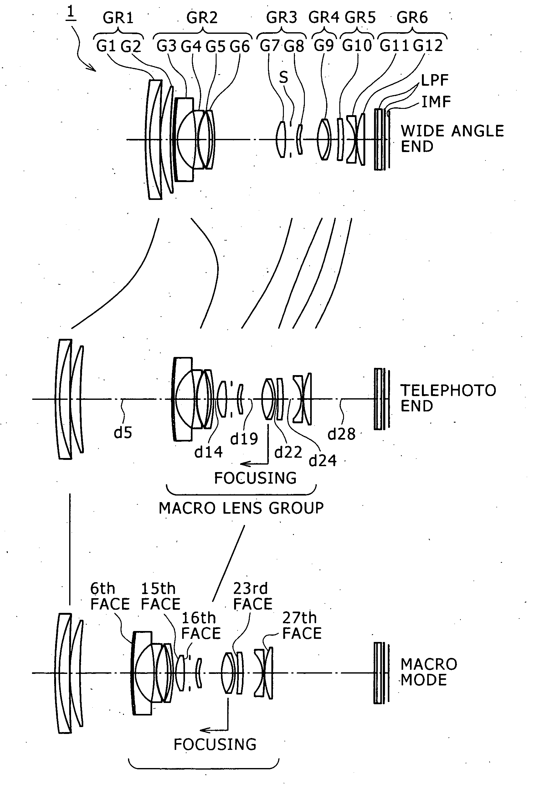
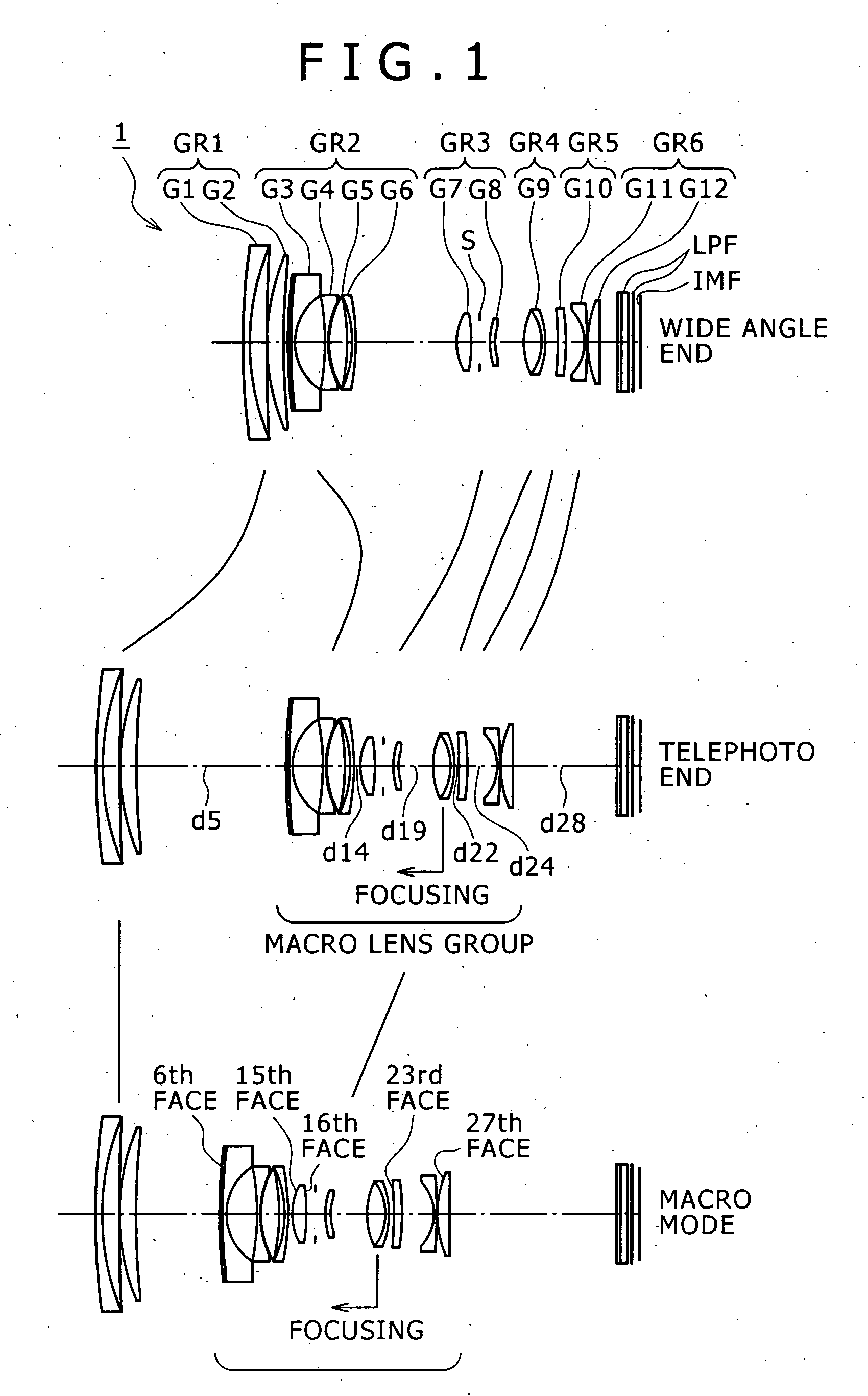
[0057]FIG. 1 shows a configuration of a zoom lens according to the present invention. Referring to FIG. 1, the zoom lens 1 shown includes a first lens group GR1 having a positive refracting power, a second lens group GR2 having a negative refracting power, a third lens group GR3 having a positive refracting power, a fourth lens group GR4 having a positive refracting power, a fifth lens group GR5 having a low refracting power, and a sixth lens group GR6 having a negative refracting power, disposed in order from the object side. Upon power variation, the lens groups move on the optical axis as indicated by a solid line arrow mark in FIG. 1.

[0058] The first lens group GR1 includes a cemented lens G1 composed of a negative lens and a positive lens, and a positive lens G2. The second lens group GR2 includes a negative lens G3 having a composite aspheric face on the object side, a negative lens G4, a positive lens G5 and another negative lens G6. The third lens group GR3 includes a positi...

second embodiment

[0066]FIG. 6 shows a configuration of a zoom lens according to the present invention. Referring to FIG. 6, the zoom lens 2 shown includes a first lens group GR1 having a positive refracting power, a second lens group GR2 having a negative refracting power, a third lens group GR3 having a positive refracting power, a fourth lens group GR4 having a positive refracting power, a fifth lens group GR5 having a low refracting power, and a sixth lens group GR6 having a negative refracting power, disposed in order from the object side. Upon power variation, the lens groups move on the optical axis as indicated by a solid line arrow mark in FIG. 6.

[0067] The first lens group GR1 includes a cemented lens G1 composed of a negative lens and a positive lens, and a positive lens G2. The second lens group GR2 includes a negative lens G3 having a composite aspheric face on the object side, a cemented lens G4 of a negative lens and a positive lens, and a negative lens G5. The third lens group GR3 inc...

third embodiment

[0074]FIG. 11 shows a configuration of a zoom lens according to the present invention. Referring to FIG. 11, the zoom lens 3 shown includes a first lens group GR1 having a positive refracting power, a second lens group GR2 having a negative refracting power, a third lens group GR3 having a positive refracting power, a fourth lens group GR4 having a positive refracting power, a fifth lens group GR5 having a low refracting power, a sixth lens group GR6 having a negative refracting power, and a seventh lens group GR7 having a positive refracting power, disposed in order from the object side. Upon power variation, the lens groups except the seventh lens group GR7 move on the optical axis as indicated by a solid line arrow mark in FIG. 11.

[0075] The first lens group GR1 includes a cemented lens G1 composed of a negative lens and a positive lens, and a positive lens G2. The second lens group GR2 includes a negative lens G3 having a composite aspheric face on the object side, a cemented le...


PUM


Abstract

A zoom lens is disclosed which has a macro mode wherein the magnifying power is higher than 0.5. The zoom lens includes a first positive lens group, a second negative lens group movable upon power variation, and a plurality of movable lens groups cooperable with the second group to form a macro lens group, disposed in order from an object side. The movable lens groups include a single focusing group, and an additional negative lens group disposed further on the image side. The zoom lens has a macro mode in which it can be focused at a shorter distance than an ordinary region by moving the macro lens group integrally from a telephoto end position toward the object side while the first lens group is fixed at the telephotograph end.

Description

CROSS REFERENCES TO RELATED APPLICATIONS [0001] The present invention contains subject matter related to Japanese Patent Application JP 2005-125957, filed in the Japanese Patent Office on Apr. 25, 2005, the entire contents of which being incorporated herein by reference. BACKGROUND OF THE INVENTION [0002] This invention relates to a novel zoom lens and image pickup apparatus, and more particularly to a zoom lens which has a macro mode and an image pickup apparatus in which the zoom lens is used. [0003] In recent years, image pickup apparatus which use a solid-state image pickup device such as digital still cameras have been and are being popularized. Above all, together with the popularization of digital still cameras, a zoom lens is demanded which is superior in compactness and has a macro mode which can implement a high image pickup magnifying power while it covers a wide range from the very wide angle side to the telephoto side by means of the single lens. [0004] Conventionally, ...

Claims


Application Information

Patent Timeline
Patent Type & Authority Applications(United States)
IPC IPC(8): G02B15/22
CPCG02B15/177G02B15/173G02B15/1461G02B15/24G02B3/0087G03B17/12H04N23/55
Inventor KURODA, DAISUKESUEYOSHI, MASAFUMI
Owner SONY CORP
Why Eureka
Try Eureka