

Thermal image forming apparatus
- Summary
- Abstract
- Description
- Claims
- Application Information
AI Technical Summary
Benefits of technology
Problems solved by technology
Method used
Image

Examples
Embodiment Construction
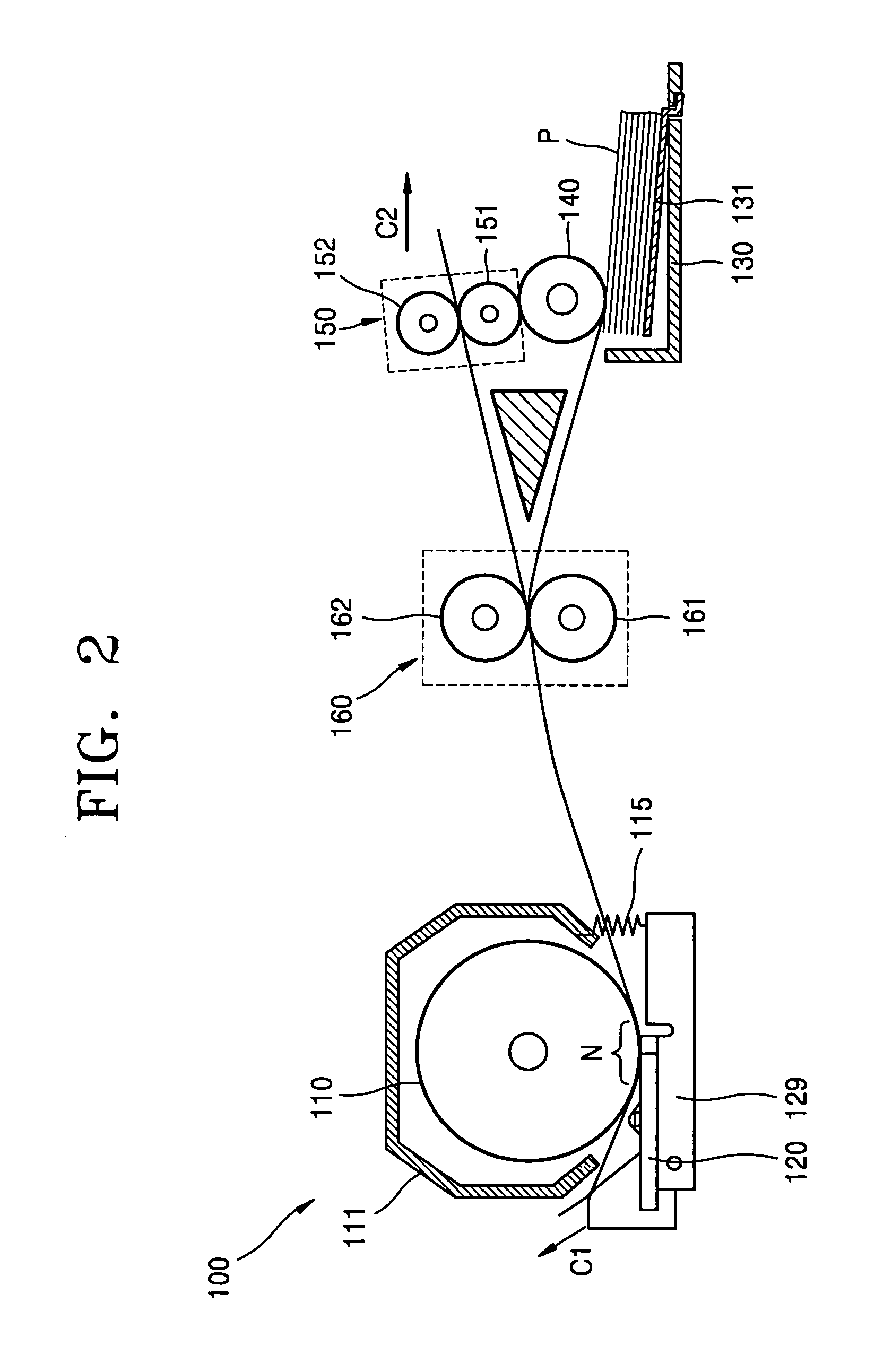
[0021]FIGS. 2 and 3 are schematic diagrams illustrating a thermal image forming apparatus 100 according to an exemplary embodiment of the present invention.
[0022] Referring to FIGS. 2 and 3, the image forming apparatus 100 includes a platen roller 110 and a thermal printhead 120. The platen roller 110 forms a printing nip N by contacting the thermal printhead 120 with a predetermined pressure. The thermal printhead is pivotally installed, and is elastically biased toward a contact direction by an elastic member 115. The elastic member 115 may be a tension spring of which a first end is connected to a holder 129 supporting the thermal printhead 120 and a second end is connected to a frame 111 enclosing a part of the platen roller 110. The thermal printhead 120 contacting the platen roller 110 may be separated from the platen roller 110 to prevent damage to a sheet of paper P when the paper P is supplied between the thermal printhead 120 and the platen roller 110. A pivot member (not...
PUM
 Abstract
Description
Claims
Application Information