Apparatus and process for gas-solids separation

Active Publication Date: 2019-04-04
UOP LLC
View PDF20 Cites 8 Cited by
  • Summary
  • Abstract
  • Description
  • Claims
  • Application Information

AI Technical Summary

Benefits of technology

[0006]Embodiments of a gas-solids separator for separating particulate matter from a gas stream are provided. A cap is pro

Problems solved by technology

It has been observed that, over the course of continuous operation over a prolonged time period on the order of several years, considerable erosion may occur within the cyclonic separator.
If

Method used


Image

  • Apparatus and process for gas-solids separation
  • Apparatus and process for gas-solids separation
  • Apparatus and process for gas-solids separation

Examples


Example

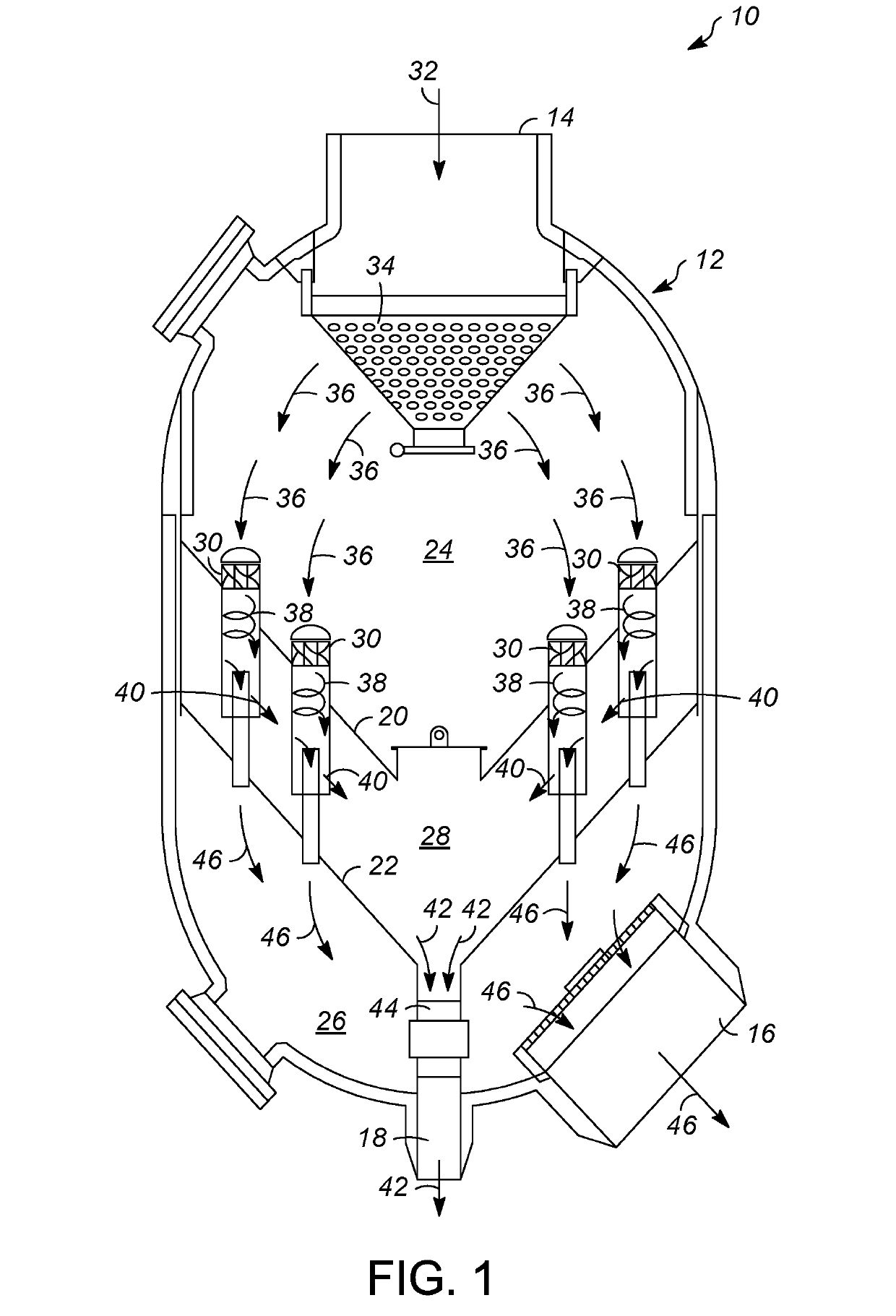
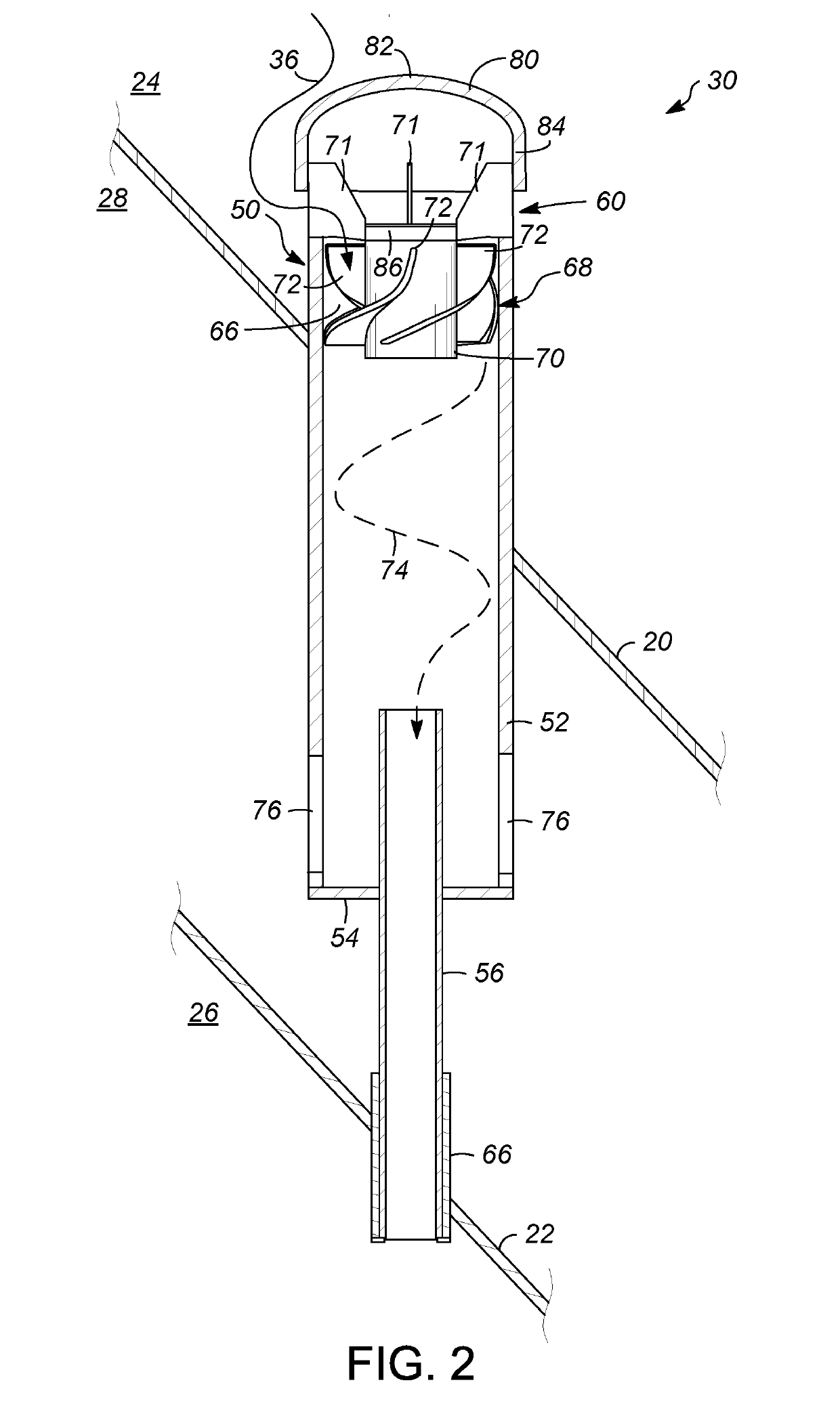
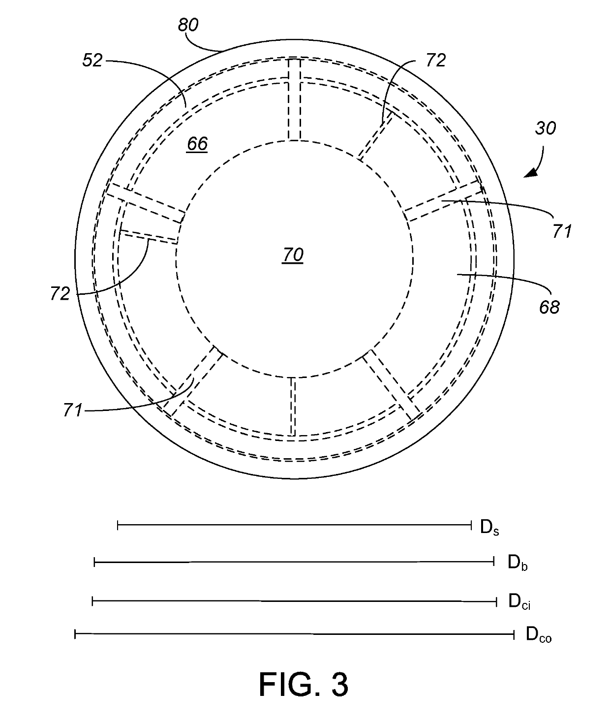
[0025]A first embodiment of the invention is a cyclonic separator, comprising a cyclone barrel; a swirl vane positioned in an upstream end of the cyclone barrel; a gas outlet centrally disposed in a downstream end of the cyclone barrel; a solids outlet peripherally disposed in the downstream end of the cyclone barrel; and a cap extending radially across an upstream end of the swirl vane. An embodiment of the invention is one, any or all of prior embodiments in this paragraph up through the first embodiment in this paragraph further comprising a plurality of swirl blades wrapped around a hub positioned in the upstream end of the cyclone barrel and the cap extends radially across an upstream end of all of the swirl vanes. An embodiment of the invention is one, any or all of prior embodiments in this paragraph up through the first embodiment in this paragraph wherein the swirl blades have upstream ends disposed circumferentially around the hub. An embodiment of the invention is one, an...

Example

[0026]A second embodiment of the invention is a gas-solids separator, comprising a vessel having a flue gas inlet, an entrained solids outlet, and a clean gas outlet; an upstream tube sheet and a downstream tube sheet within the vessel and defining therewith a gas inlet chamber fluidly coupled to the flue gas inlet, an entrained solids chamber fluidly coupled to the entrained solids outlet, and a clean gas chamber fluidly coupled to the clean gas outlet; and a cyclonic separator, comprising a cyclone barrel extending into the entrained solids chamber and fluidly coupled to the flue gas inlet; a swirl vane positioned in an upstream end of the cyclone barrel; a gas outlet centrally disposed in a downstream end of the cyclone barrel and fluidly coupling the gas inlet chamber to the clean gas chamber; a solids outlet peripherally disposed in the downstream end of the cyclone barrel and fluidly connected to the entrained solids outlet; and a cap extending radially above an upstream end o...

Example

[0027]A third embodiment of the invention is a process for separating solids from gas comprising directing a solid-laden gas to a cyclonic separator; shielding direct entry into the cyclonic separator that includes swirl vane with a cap; limiting the solid-laden gas access to the swirl blades but around a downstream end of the cap; contacting the solid-laden gas with swirl blades which induce the solid laden gas to swirl in a cyclone; and separating solids from the gas by centripetal acceleration. An embodiment of the invention is one, any or all of prior embodiments in this paragraph up through the third embodiment in this paragraph further comprising directing the solid-laden gas from a flue gas inlet to a vessel to the cyclonic separator in the vessel, and wherein the solids exit the vessel through an entrained solids outlet, and the gas exits the vessel through a clean gas outlet.

[0028]Without further elaboration, it is believed that using the preceding description that one skil...


PUM


Abstract

A process and apparatus of a gas-solids separator are provided in which a cap is disposed across an upstream end of swirl blades in a cyclonic separator to protect the blades from erosion by fast traveling solids.

Description

FIELD[0001]The field relates to gas-solids separators well-suited for usage within fluid catalytic cracking units.DESCRIPTION OF RELATED ART[0002]Fluid catalytic cracking (FCC) is a widely-utilized process wherein a heavy hydrocarbon feed is contacted with a catalyst under elevated temperature within a main reactor to yield lighter hydrocarbon products. During the cracking process, catalyst activity gradually decreases due to the deposition of coke on the catalyst granules. To restore catalyst activity, the spent catalyst is continually withdrawn from the main reactor through a spent catalyst standpipe and supplied to a catalyst regenerator in which combustion occurs to burn-off the coke deposits. The regenerated catalyst is then recycled to the riser of the main reactor to again contact the heavy hydrocarbon feed and repeat the cracking process. The flue gas generated as a result of combustion within the catalyst regenerator is collected within an upstream manifold and, depending u...

Claims


Application Information

Patent Timeline
IPC IPC(8): B04C3/04B04C3/06B04C9/00B01D45/14
CPCB04C3/04B04C3/06B04C9/00B01D45/14B04C2003/006B04C2009/007B01D45/16B01D45/12B04C3/00B01J8/0055
Inventor KRISHNAMURTHY, SUJAY R.THRONDSON, ROGER L.ALTHOFF, JAMES W.JOHNSON, II, RICHARD A.
Owner UOP LLC
Why Eureka
Try Eureka