Vehicle door structure

Inactive Publication Date: 2016-04-28
TOYOTA IND CORP
View PDF9 Cites 9 Cited by
  • Summary
  • Abstract
  • Description
  • Claims
  • Application Information

AI Technical Summary

Benefits of technology

[0008]In the vehicle door structure, the arm portion is disposed, on at least one of the sliding door and the body portion, to be turnable around the shaft parallel to the rotary axes of the first rollers. Accordingly, in this vehicle door structure, even when the sliding door inclines relative to the opening-and-closing direction, the arm portion turns around the shaft with respect to the sliding door and/or the body portion. Therefore, the body portion that supports each of the rollers is not interlocked with operation of the sliding door. As a result, the body portion is not affected by the inclination of the sliding door. In the guide body, the two or more first rollers are disposed so as to be spaced apart at the predetermined interval in the extending direction of the slide rail. Thus, even when the arm portion turns, an attitude of the body portion can be stably maintained. As a result, the vehicle door structure can prevent a defect caused by contact between the rollers of the guide body and the slide rail in the sliding mechanism.
[0009]In one embodiment, the arm portion may be disposed on the body portion to be turnable around the shaft. Accordingly, in the vehicle door structure, even when the sliding door inclines, the arm portion turns with respect to the body portion. Thus, the attitude of the body portion can be maintained. As a result, contact between an upper surface or a lower surface of the slide rail and a member other than the first roller, such as the second roller, can be prevented.
[0010]In one embodiment, the arm portion may be coupled to a position between the two first rollers in the body portion. As described above, co

Problems solved by technology

Therefore, there is a risk that a member other than a first roller, such as a second roller, comes in contact with an upper surface or a lower surface of a slide rail.
Therefore, contact of a member other than the first rolle

Method used


Image

  • Vehicle door structure
  • Vehicle door structure
  • Vehicle door structure

Examples


Example

[0024]A preferred embodiment of the present invention will be described in detail below with reference to the attached drawings. Note that the same or similar elements in the description of the drawings are denoted with the same reference signs, and the duplicate descriptions thereof are omitted. In the following description, a front-and-back direction, a width direction, and a height direction of a vehicle (automobile) 100 are defined as front-and-back, right-and-left, and up-and-down, respectively.

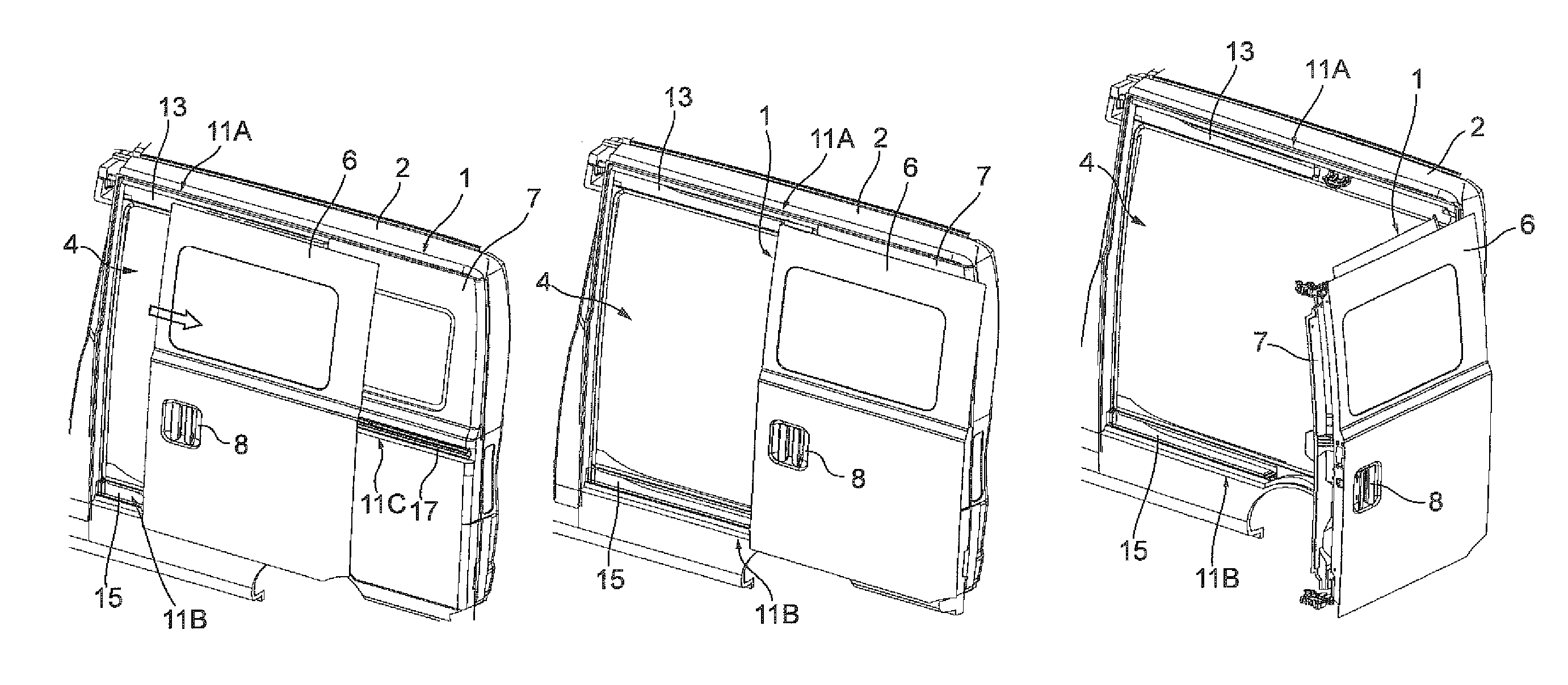
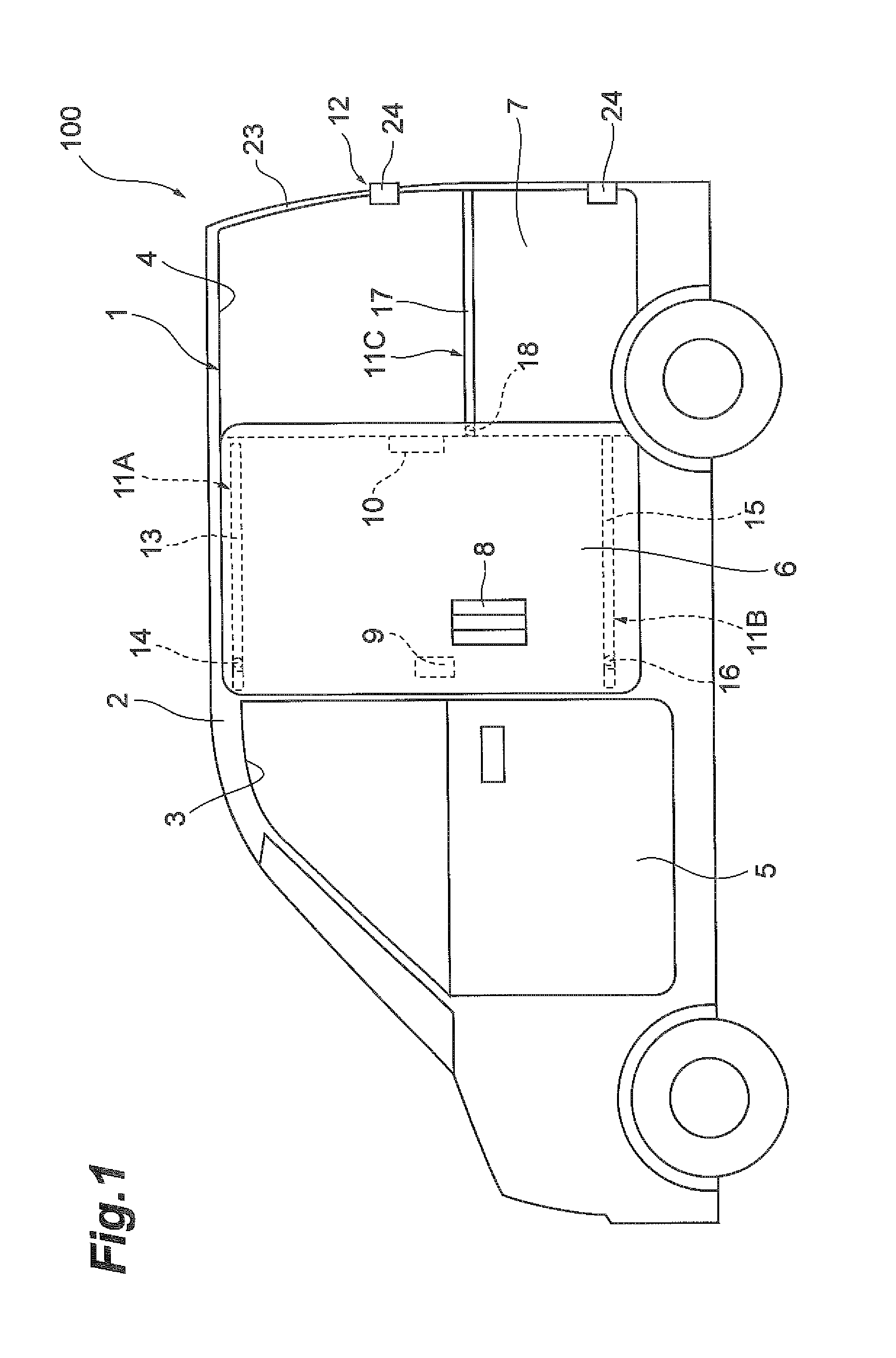
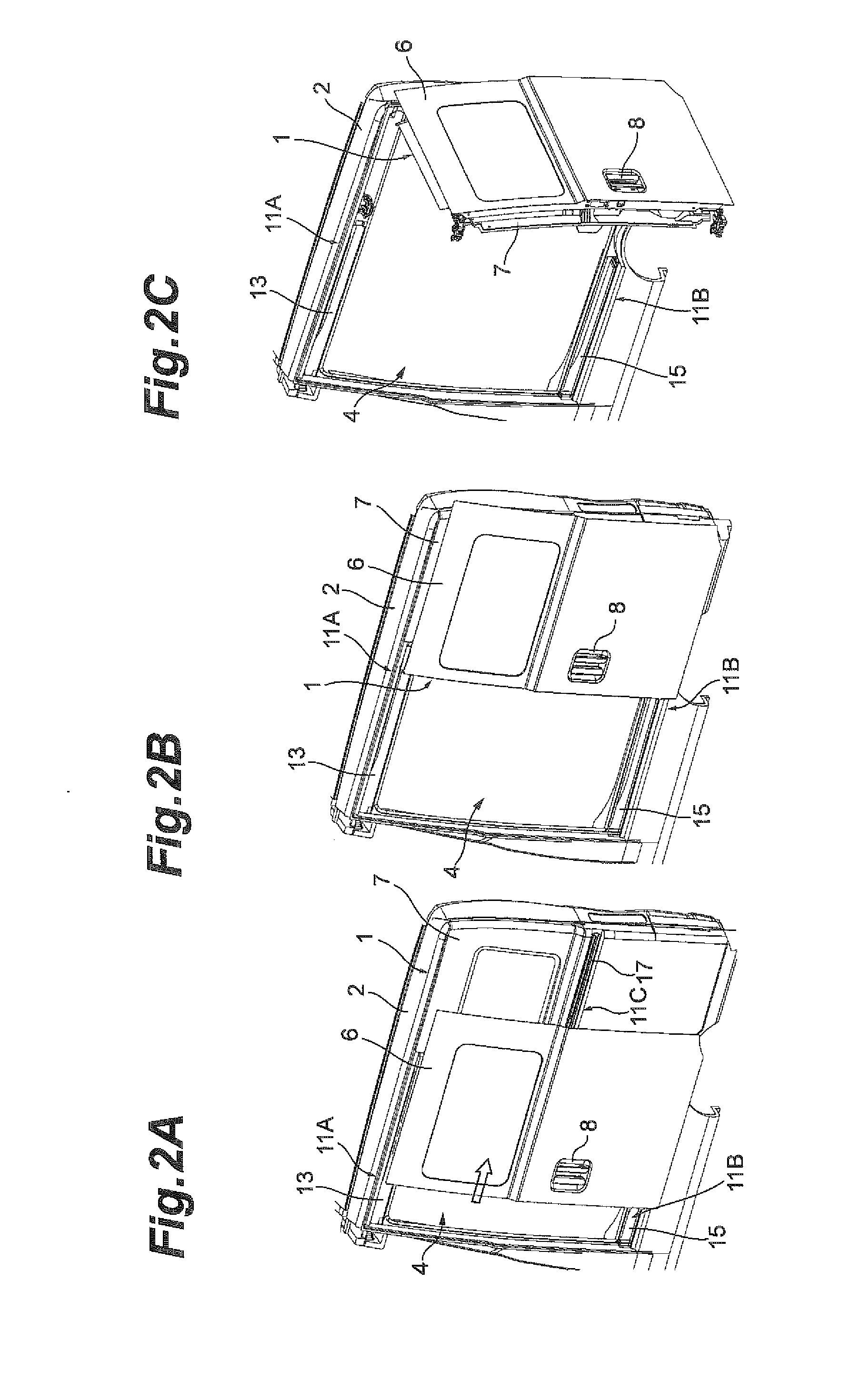
[0025]FIG. 1 is a side view of the vehicle including a vehicle door structure according to an embodiment. As shown in FIG. 1, the vehicle door structure 1 is disposed in the vehicle 100. In the present embodiment, the vehicle door structure 1 is disposed on a side portion of a vehicle body 2. A front door opening 3 and a rear door opening 4 are formed in the side portion of the vehicle body 2. The front door opening 3 is positioned on a side of a front seat. The rear door opening 4 is po...


PUM


Abstract

A vehicle door structure includes a sliding door configured to open and close a door opening formed in a side portion of a vehicle body, and a slide supporting mechanism configured to slide the sliding door. The slide supporting mechanism includes a middle slide rail disposed so as to extend in an opening-and-closing direction of the sliding door, and a guide body that is guided by the middle slide rail. The guide body includes two first rollers, two second rollers, a body portion, and an arm portion. The body portion rotatably supports the two first rollers and the two second rollers. The arm portion couples the sliding door and the body portion. The arm portion is disposed, on at least one of the sliding door and the body portion, to be turnable around a shaft parallel to rotary axes of the first rollers.

Description

BACKGROUND OF THE INVENTION[0001]1. Field of the Invention[0002]The present invention relates to a vehicle door structure.[0003]2. Related Background Art[0004]The structure described in JP 2013-227816 A has been known as a vehicle door structure in the related art. The vehicle door structure described in JP 2013-227816 A includes a sliding door for opening and closing an opening formed in a side portion of a vehicle body. The sliding door slides in a front-and-back direction of the vehicle body through a sliding mechanism. The sliding mechanism includes a slide rail and a roller unit (guide body). The slide rail is disposed so as to extend in an opening-and-closing direction of the sliding door. The slide rail guides the roller unit. The roller unit is fixed to the sliding door. The roller unit includes a first roller and two second rollers. The first roller regulates a movement in a height direction of the vehicle body in the slide rail. The second rollers regulate a movement in a ...

Claims


Application Information

Patent Timeline
IPC IPC(8): B60J5/04E06B3/52B60J5/06E06B3/50
CPCB60J5/047E06B3/5072B60J5/06E06B3/52E06B3/509E05D15/101E05Y2900/531E05D15/0608
Inventor MARUYAMA, KATSUYAKUNO, HIROSHI
Owner TOYOTA IND CORP
Why Eureka
Try Eureka