
Burner device

Active Publication Date: 2020-08-20
KAWASAKI HEAVY IND LTD +1
View PDF0 Cites 0 Cited by
  • Summary
  • Abstract
  • Description
  • Claims
  • Application Information

AI Technical Summary

Benefits of technology

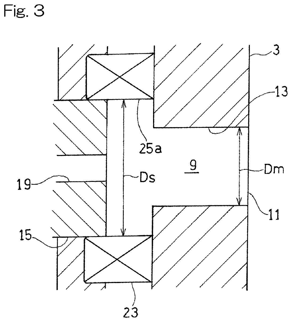
The present invention provides a burner device that can stably form a lifted flame. By applying combustion-supporting gas directly to the fuel gas injected from the fuel gas injection nozzle, a space, from a portion at which the fuel gas is injected, to the combustion region becomes unstable, and a lifted flame is likely to be formed. The combination of swirling flow from the combustion-supporting gas supply swirler and reduced width of the combustion-supporting gas flow path facilitates the formation of a lifted flame. Additionally, the diameter of the mixture injection outlet should be less than the diameter of the combustion-supporting gas supply swirler to increase the flow rate of the mixture. Overall, this burner device provides a stable and efficient flame for industrial applications.

Problems solved by technology

However, when a fuel having a high combustion speed is burned, NOx is likely to be generated.
When a fuel having a high combustion speed is burned, backfire phenomenon in which flame generated in a combustion chamber is returned to the burner side is likely to occur.
A burner having a conventional structure has difficulty in stably forming and maintaining the lifted flame, and is difficult to use for an actual device such as a gas turbine and a boiler in which an operation condition is not always constant.

Method used


Image

  • Burner device
  • Burner device
  • Burner device

Examples


Embodiment Construction

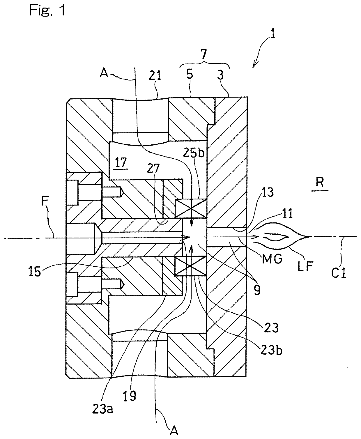
[0023]A preferred embodiment of the present invention will be described below with reference to the drawings. FIG. 1 shows a burner device 1 according to one embodiment of the present invention. The burner device 1 shown in FIG. 1 supplies a mixture MG of a fuel gas and a combustion-supporting gas to a combustion region R. The burner device 1 is used as, for example, a heating device for a power unit such as a gas turbine and a boiler.

[0024]The fuel gas may be, for example, a fuel that has a high combustion speed and a wide range of combustible concentrations. In the present embodiment, a hydrogen-containing gas such as a hydrogen gas is used as the fuel gas. In the present embodiment, an air A is used as the combustion-supporting gas. Other than air, for example, a gas in which the oxygen concentration in the air is adjusted or an exhaust gas may be used as the combustion-supporting gas. In the following description, the fuel gas is represented as “fuel F” and the combustion-suppor...


PUM


Abstract

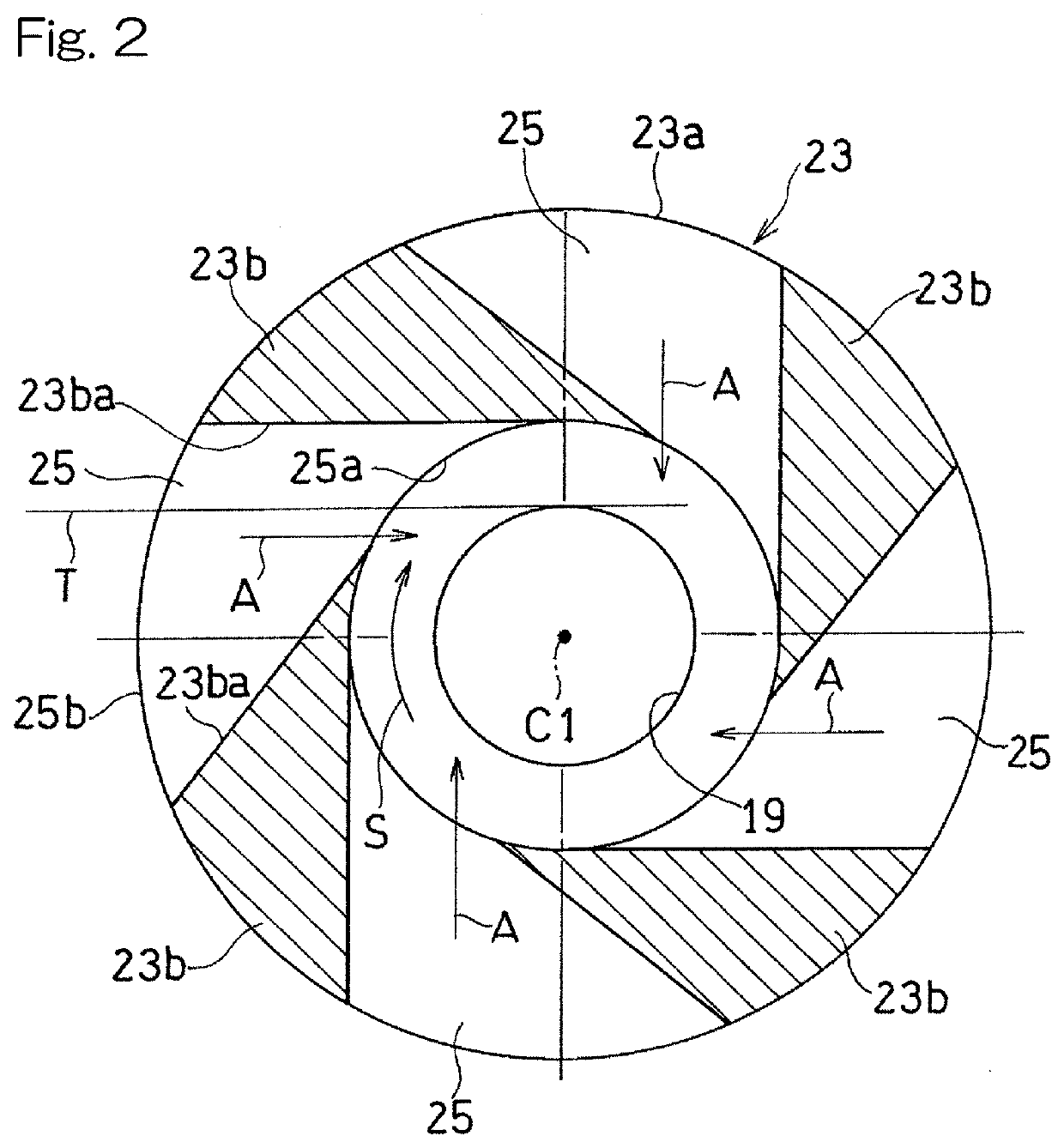
A burner device for supplying a mixture of a fuel gas and a combustion-supporting gas into a combustion region includes: a mixing path configured to inject the mixture from a downstream end portion of the mixing path into the combustion region; a fuel gas injection nozzle configured to inject the fuel gas into the mixing path toward the combustion region; and a combustion-supporting gas supply swirler configured to inject the combustion-supporting gas such that at least a part of the combustion-supporting gas collides directly with the fuel gas injected from the fuel gas injection nozzle, in a direction of a tangent line that is tangent to a fuel injection hole of the fuel gas injection nozzle on a cross-section.

Description

CROSS REFERENCE TO THE RELATED APPLICATION[0001]This application is a continuation application, under 35 U.S.C. § 111(a), of international application No. PCT / JP2018 / 041366, filed Nov. 7, 2018, which claims priority to Japanese patent application No. 2017-215851, filed Nov. 8, 2017, the entire disclosures of all of which are herein incorporated by reference as a part of this application.BACKGROUND OF THE INVENTIONField of the Invention[0002]The present invention relates to a burner device for mixing and burning, for example, a fuel gas such as hydrogen gas and another kind of gas.Description of Related Art[0003]In recent years, a burner device that utilizes hydrogen as fuel has been suggested for realizing a so-called low-carbon society in order to reduce emissions of carbon dioxide that causes environmental issues such as global warming (for example, see Patent Document 1).RELATED DOCUMENTPatent Document[0004][Patent Document 1] U.S. Patent Application Publication No. 2012 / 0258409S...

Claims


Application Information

Patent Timeline
IPC IPC(8): F23D14/02F23D14/64
CPCF23D2900/14021F23D2205/00F23D14/02F23D2203/007F23D14/64F23D14/48F23C7/004
Inventor ODA, TAKEOSAKURAZAWA, TOSHIAKIOSHIMA, RYOSUKEYUASA, SABUROSAKURAI, TAKASHINOZAKI, KOICHI
Owner KAWASAKI HEAVY IND LTD
Learn More