
Internal antenna having surface-mounted receptacle

Inactive Publication Date: 2009-04-02
ACE ANTENNA
View PDF5 Cites 3 Cited by
  • Summary
  • Abstract
  • Description
  • Claims
  • Application Information

AI Technical Summary

Benefits of technology

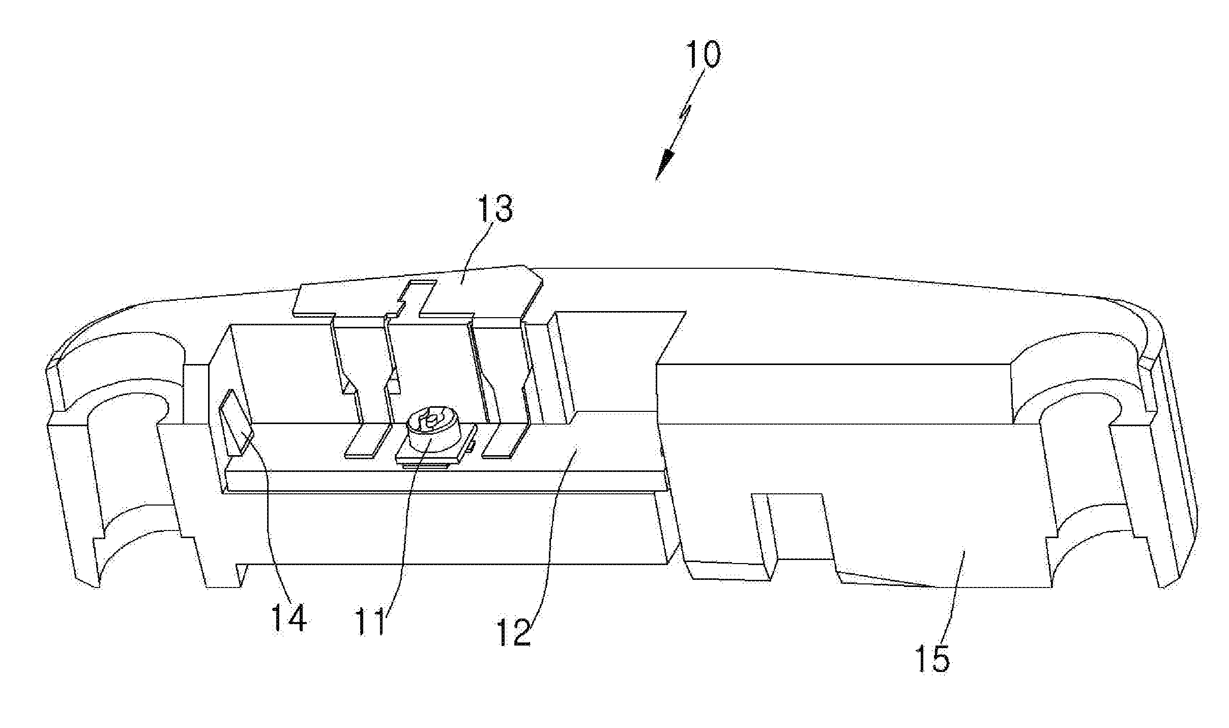
[0011]Accordingly, the present invention has been made keeping in mind the above problems occurring in the prior art, and the present invention provides an internal antenna having a surface-mounted receptacle and a radiator, which is configured such that a terminal part extends from a radiation part, is electrically connected to a printed circuit board on which a feeding pattern and a ground pattern are formed. Thus, not only are manufacturing costs reduced thanks to the reduction in the number of components, but also the manufacturing process is simplified. In addition, the electrical connection between the printed circuit board and the radiator is stably maintained.

Problems solved by technology

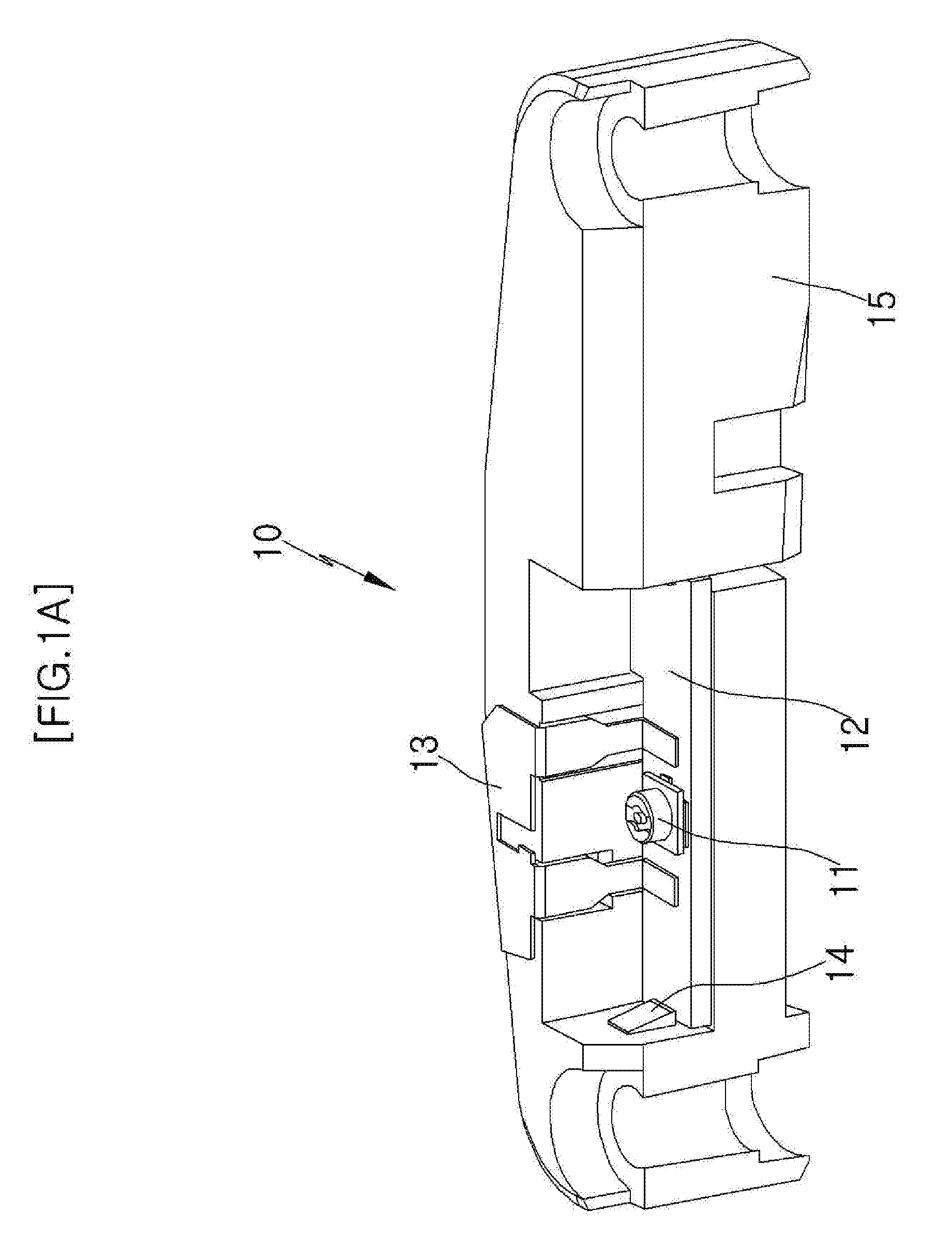
However, in the conventional internal antenna of FIG. 1A, a malfunction may occur due to cold solder joints between the printed circuit board 12 and the radiator 13.
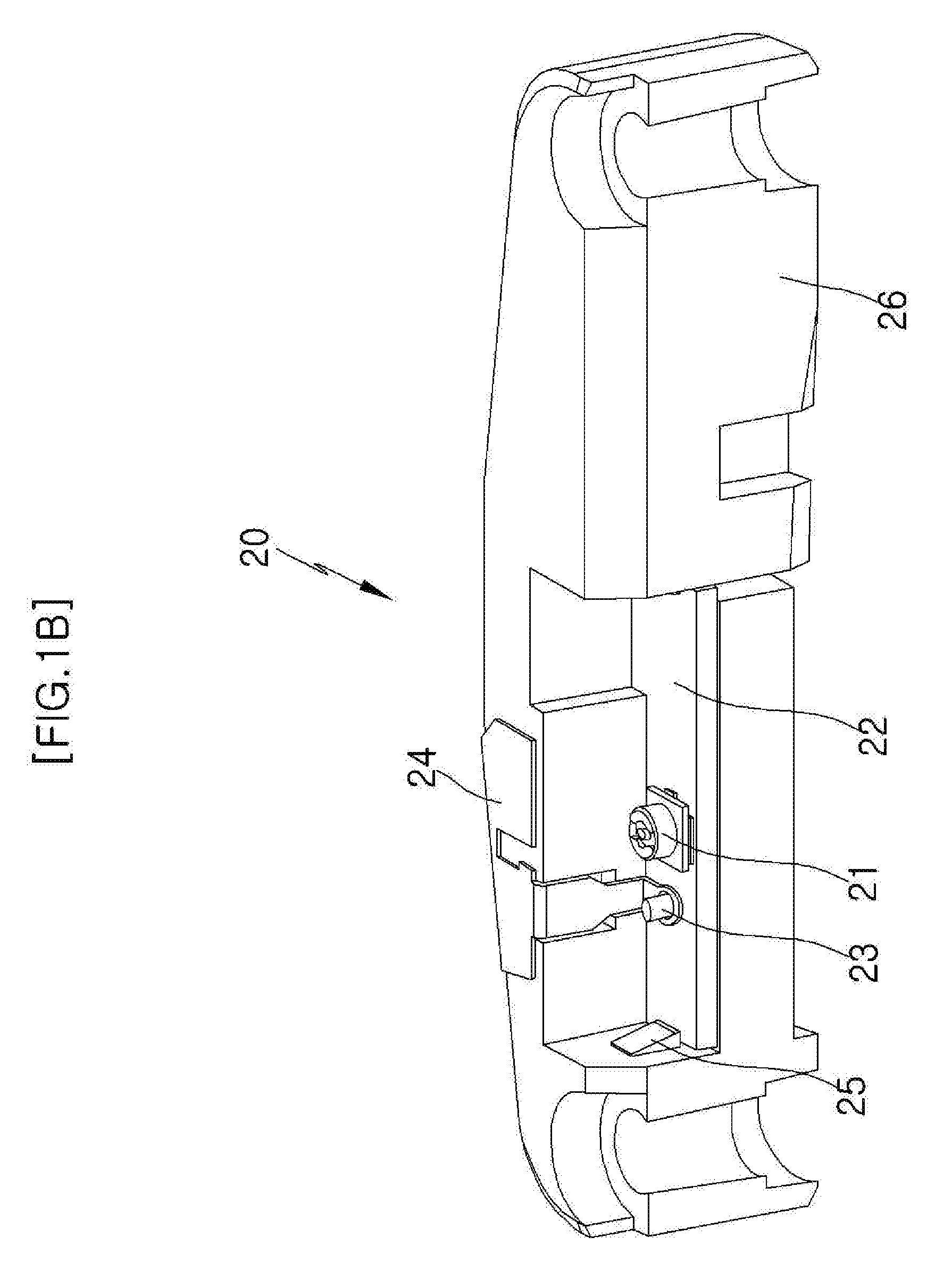
Furthermore, in the conventional internal antenna of FIG. 1B, a connection method using the pin 23 is used, so that an electrical connection malfunction may occur if the pin 23 becomes damaged in the process of compressing the pin 23 or if the pin oscillates, which decreases phone call quality.

Method used


Image

  • Internal antenna having surface-mounted receptacle
  • Internal antenna having surface-mounted receptacle
  • Internal antenna having surface-mounted receptacle

Examples


first embodiment

[0047]In the first embodiment described above, the respective feeding and ground terminals 134 and 135 of the radiator 130, which exert the downward force, are electrically connected to the first feeding pattern 122 and the first ground pattern 123, so that reliable phone call quality can be provided thanks to the stable connection.

[0048]FIG. 3A is a view showing the construction of an internal antenna having a surface-mounted receptacle according to another embodiment of the present invention. The internal antenna includes a printed circuit board 220, which is configured such that a receptacle 210 is surface-mounted thereon, a radiator 230, which is electrically connected to the lower surface of the printed circuit board 220, and a frame 240, which is configured such that the printed circuit board 220 and the radiator 230 are mounted thereto.

[0049]The electrical connection between the printed circuit board 120 and the radiator 130, shown in the FIG. 2A, is made on the upper surface...

second embodiment

[0060]In the second embodiment described above, the respective feeding and ground terminals 234 and 235 of the radiator 230, which exert the upward force, are electrically connected to the second feeding pattern 225 and the second ground pattern 226 formed on the lower surface of the frame 240, so that reliable phone call quality can be provided thanks to the stable connection.

[0061]Accordingly, in the above embodiments, the first feeding patterns 122 and 222 and the second feeding patterns 125 and 225 formed on the upper surfaces of the printed circuit boards 120 and 220, are electrically connected with the first ground patterns 123 and 223 and the second ground patterns 126 and 226 formed on the lower surfaces of the printed circuit boards 120 and 220, via the through-holes 124 and 224, which are formed in the respective printed circuit boards 120 and 220. This enables the feeding terminals 134 and 234 and the ground terminals 135 and 235 of the radiators 130 and 230 to perform th...


PUM


Abstract

Disclosed herein is an internal antenna having a surface-mounted receptacle. The internal antenna includes a printed circuit board, a radiator, and a frame. The printed circuit board is configured such that a receptacle is surface-mounted thereon. The radiator is connected to the printed circuit board. The frame is configured such that the printed circuit board and the radiator are mounted thereto.

Description

BACKGROUND OF THE INVENTION[0001]1. Field of the Invention[0002]The present invention relates generally to mobile terminal internal antennas, and more particularly, to an internal antenna having a surface-mounted receptacle, which is configured such that the receptacle is surface-mounted on a printed circuit board. A feeding pattern and a ground pattern are formed on the printed circuit board, which is provided with a radiator having a terminal part that is electrically connected to the feeding pattern and the ground pattern, and which is also connected with a cable via the receptacle mounted in the internal antenna, so as to be connected with the main board of a mobile terminal.[0003]2. Description of the Related Art[0004]Current mobile terminal internal antennas which are configured so as to be separated from the main board of the mobile terminal are connected to the main board using a cable.[0005]In this case, in order to make a connection between the internal antenna and the cab...

Claims


Application Information

Patent Timeline
IPC IPC(8): H01Q1/24
CPCH01Q1/243H01Q1/1207H01Q1/38H01Q9/0407
Inventor SO, SOON-JONGMUN, SANG-HYUKSEO, SUK-HWANHAN, JI-SOO
Owner ACE ANTENNA
Learn More