Seal assembly for a rotary machine

Active Publication Date: 2019-07-04
GENERAL ELECTRIC CO
View PDF0 Cites 13 Cited by
  • Summary
  • Abstract
  • Description
  • Claims
  • Application Information

AI Technical Summary

Benefits of technology

[0009]In one embodiment, a seal segment of a seal assembly configured to extend around a rotating component of a rotary machine between the rotating component and a stator interface is provided. The seal segment includes a film-riding shoe having one or more internal passages and an aft plate coupled with the film-riding shoe. The one or more internal passages are configured to direct pressurized fluid in the rotary machine to a location between the film-riding shoe and the rotating compo

Problems solved by technology

Increased leakage between rotors and stators can significantly reduce the power generated by the rotary machines; thereby lowering the operating efficiency of the rotary machines.
Labyrinth seals that are assembled with

Method used


Image

  • Seal assembly for a rotary machine
  • Seal assembly for a rotary machine
  • Seal assembly for a rotary machine

Examples


Example

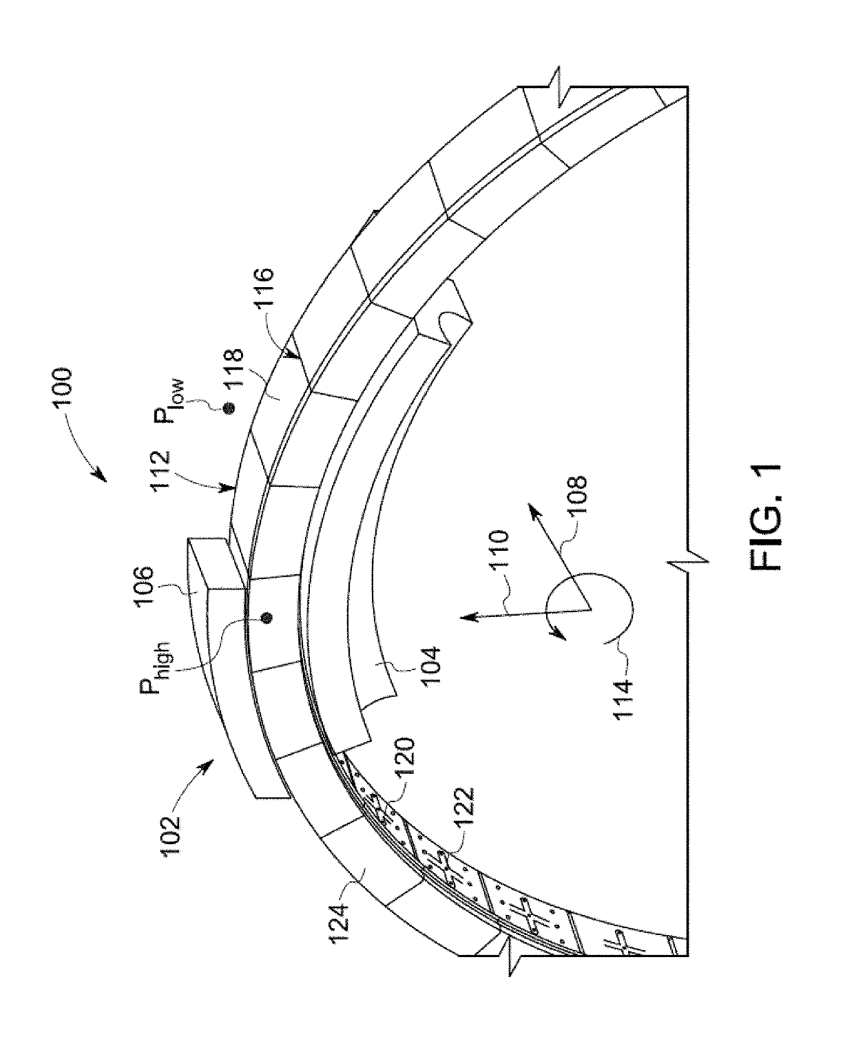
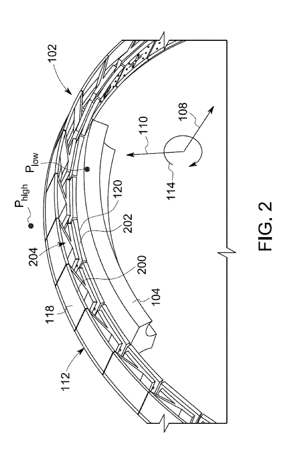
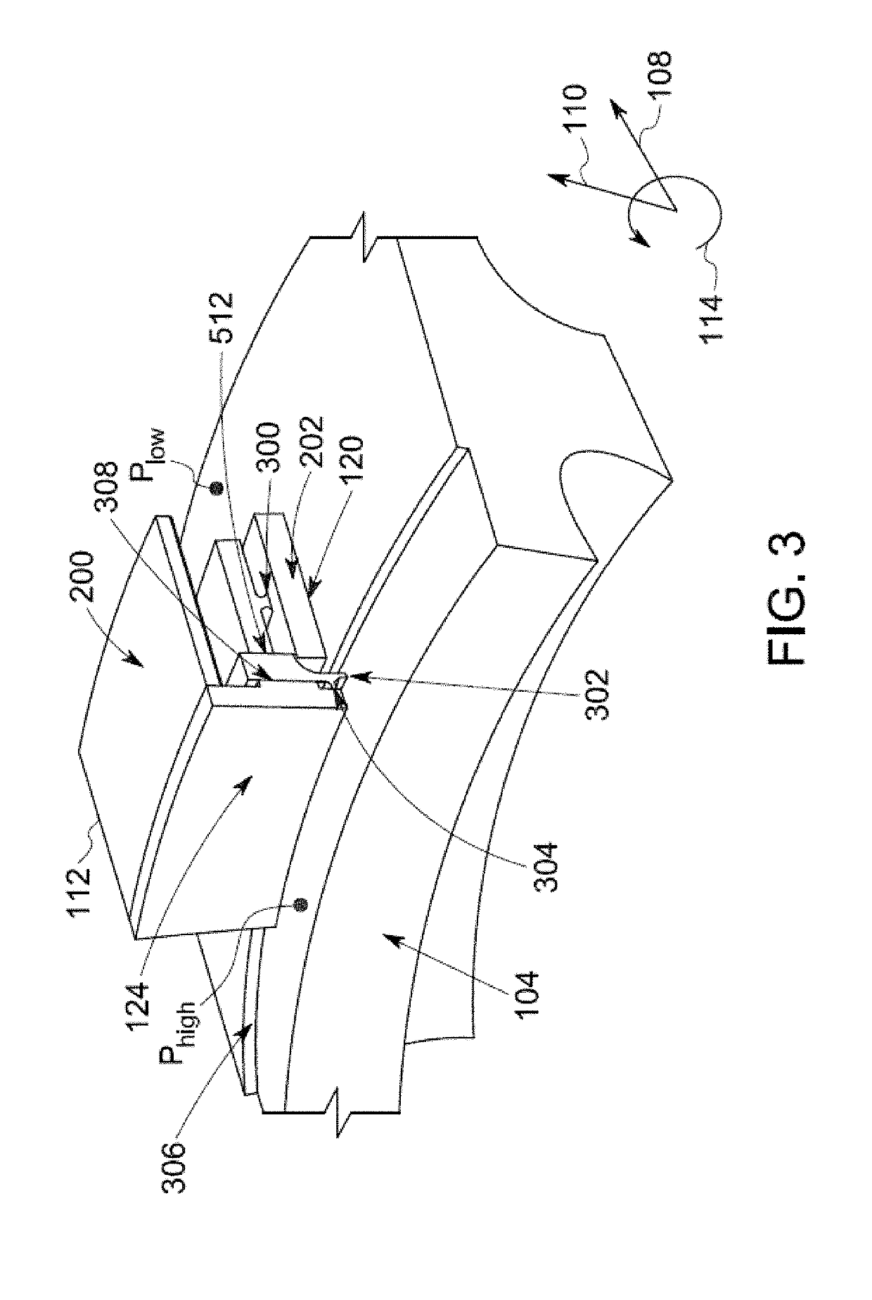
[0052]One or more embodiments of the inventive subject matter described herein provide seal assemblies for rotary machines. The seal assemblies are film-riding hybrid aerostatic-aerodynamic seals for sealing rotor-stator circumferential gaps in gas turbines, steam turbines, aircraft engines, supercritical CO2 turbines, centrifugal compressors, and other rotary machinery. As used herein, the terms “aerostatic” and “aerodynamic” are used to refer to the types of load-bearing pressures in a fluid film formed between the seal assembly and a rotor. The aerostatic forces are fluid film forces created due to pressurization and are thus pressure-dependent in nature. The aerodynamic forces are forces in the fluid film that are dependent on the speed at which the rotor rotates. The term “aero” or fluid should not restrict all embodiments of the inventive subject matter described herein to air as the working fluid. The seal assemblies can operate with other working fluids such as nitrogen, hyd...


PUM


Abstract

A seal assembly of a rotary includes a radially oriented plate that axially opposes a front and rear support plates of a stator interface. The seal assembly also includes a film-riding shoe coupled with the radially oriented plate. The shoe forms a shoe fluid bearing between the shoe and a rotating component responsive to rotation of the rotating component and pressurization of fluid in the rotary machine upstream of the stator interface. One or more of the stator interface or the film-riding shoe includes one or more ports or pathways through which higher-pressure fluid upstream of the stator housing in the rotary machine flows to form an aft axial fluid bearing between the radially oriented plate and the rear support plate of the stator interface.

Description

CROSS-REFERENCE TO RELATED APPLICATIONS[0001]This application is a continuation-in-part of U.S. patent application Ser. No. 15 / 697,062, filed 6 Sep. 2017, the entire disclosure of which is incorporated herein by reference.GOVERNMENT LICENSE RIGHTS[0002]This invention was made with government support under contract number DE-FE0024007 awarded by the U.S. Department Of Energy. The government has certain rights in the invention.FIELD[0003]The subject matter described herein relates to seal assemblies in rotary machines.BACKGROUND[0004]Many rotary machines, such as gas turbines, steam turbines, aircraft engines, supercritical CO2 turbines, compressors and other rotary machines, have seals between the moving components (e.g., rotors) and the stationary components (e.g., stators). These seals help to reduce leakage of fluids between the rotors and stators. Increased leakage between rotors and stators can significantly reduce the power generated by the rotary machines; thereby lowering the...

Claims


Application Information

Patent Timeline
IPC IPC(8): F16J15/447F01D11/02F01D11/08
CPCF16J15/4476F01D11/02F01D11/08F01D11/025F01D11/003F16J15/442
Inventor BIDKAR, RAHUL ANILJOHNSON, STEVEN DOUGLASGIBSON, NATHAN EVAN MCCURDY
Owner GENERAL ELECTRIC CO
Why Eureka
Try Eureka