Apparatus And Method For Holding A Cryogenic Fluid And Removing Cryogenic Fluid Therefrom With Reduced Heat Leak

Active Publication Date: 2007-01-04
WESTPORT FUEL SYST CANADA INC
View PDF12 Cites 24 Cited by
  • Summary
  • Abstract
  • Description
  • Claims
  • Application Information

AI Technical Summary

Benefits of technology

[0024] (b) thermally insulating the pump to reduce heat leak into the cryogen space by connecting the pump to a drive unit external to the vessel with an elongated member compr

Problems solved by technology

Higher storage density is desirable, for example, when the gas is employed as a fuel for a vehicle because the space available to store fuel on board a vehicle can be limited.
Compressed gases are commonly stored at pressures above 20 MPa (about 3000 psig), but vessels that are rated for containing gases at such high pressures require a structural strength that can add weight and cost to the vessel.
In addition, because of the lower storage density of gas stored in the gaseous phase, the size and/or number of vessels must be larger to hold the same molar quantity of gas and this adds to the weight of the storage vessels if the gas is stored in the gaseous phase.
Extra weight adds to operational costs if the vessel is used in a mobile application, either for holding a liquefied gas for transporting it, or for holding the gas on board for use as a fuel to be consumed by the vehicle's engine.
A problem with storing a liquefied gas at cryogenic temperatures is providing sufficient thermal insulation to prevent heat transfer into the cryogen space.
One of the prob

Method used


Image

  • Apparatus And Method For Holding A Cryogenic Fluid And Removing Cryogenic Fluid Therefrom With Reduced Heat Leak
  • Apparatus And Method For Holding A Cryogenic Fluid And Removing Cryogenic Fluid Therefrom With Reduced Heat Leak
  • Apparatus And Method For Holding A Cryogenic Fluid And Removing Cryogenic Fluid Therefrom With Reduced Heat Leak

Examples


Embodiment Construction

)

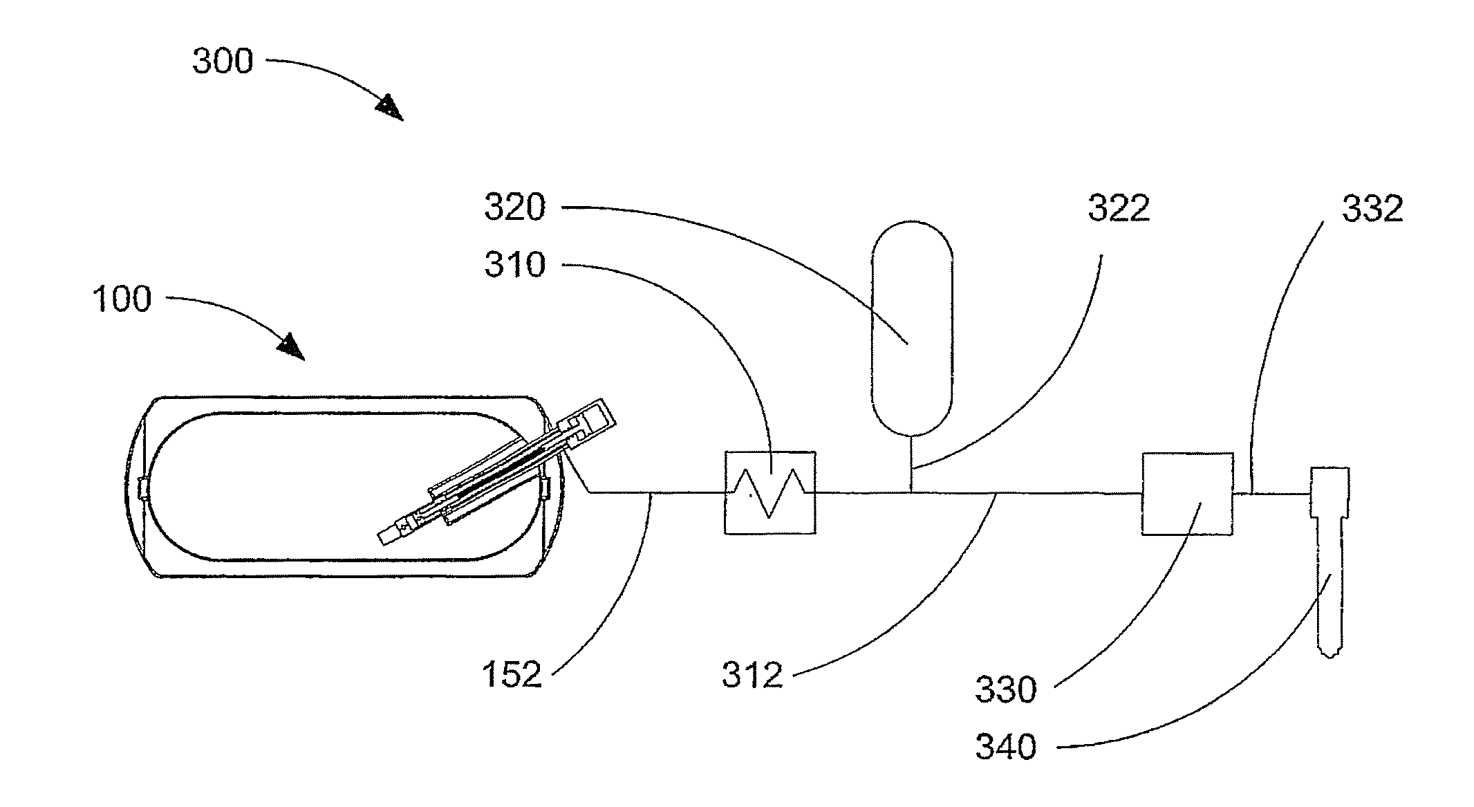
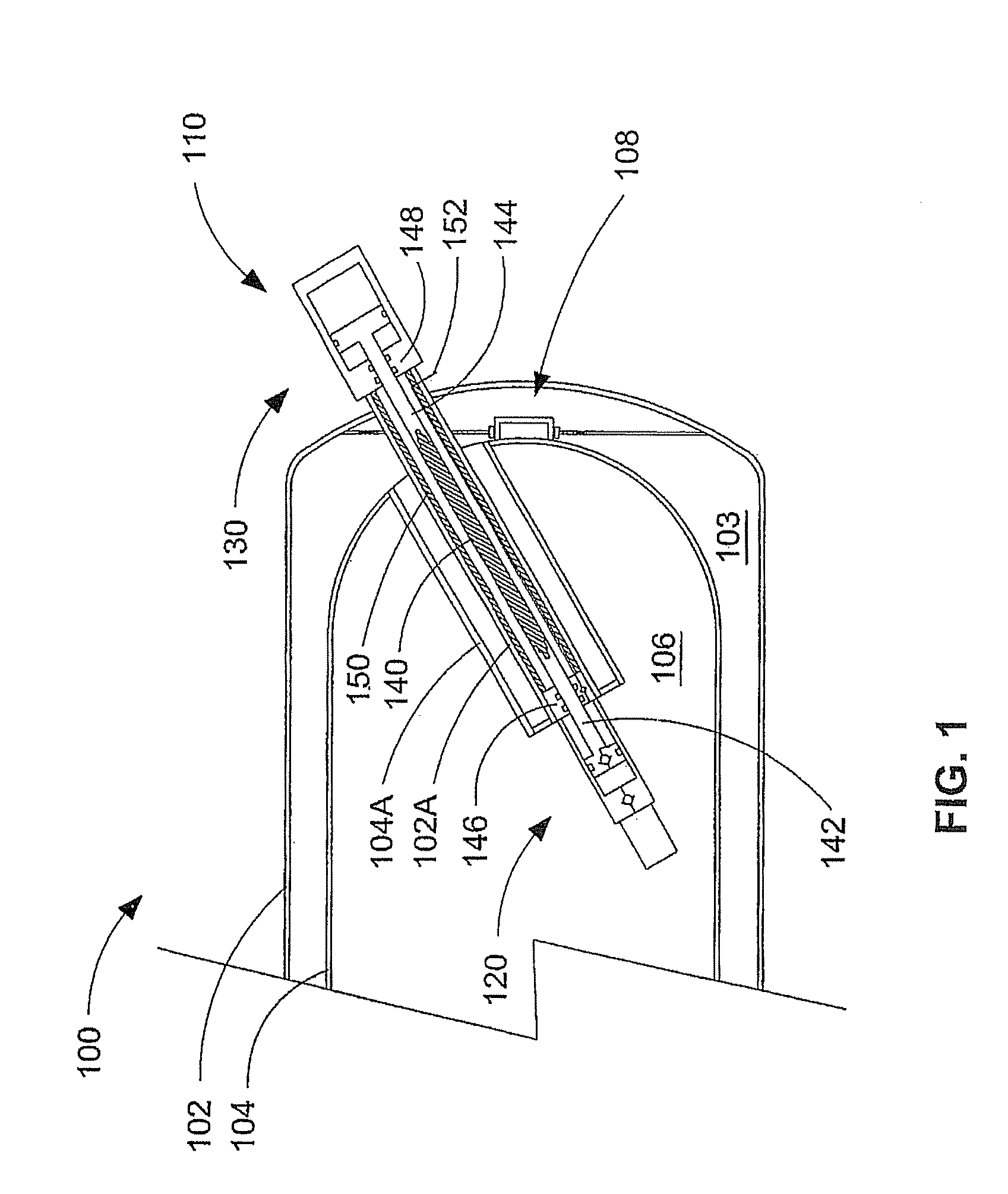
[0030]FIG. 1 is a cross section view showing the general arrangement of a portion of an apparatus 100 that comprises a thermally insulated storage vessel and a pump disposed inside the storage vessel. The illustrated storage vessel has a double-walled construction with an outer wall 102 and an inner wall 104. The space between outer wall 102 and inner wall 104 can be evacuated to provide vacuum space 103 for thermally insulating cryogen space 106, defined by the inner surface of inner wall 104. There are a number of known arrangements for supporting inner wall 104 within outer wall 102 and support structure 108 is merely representative of one such arrangement. For mobile storage vessels, the support structure must be able to handle shifts in the loading caused by movement of the vehicle, and the supports must be designed to carry the full dynamic load in both the axial and radial directions.

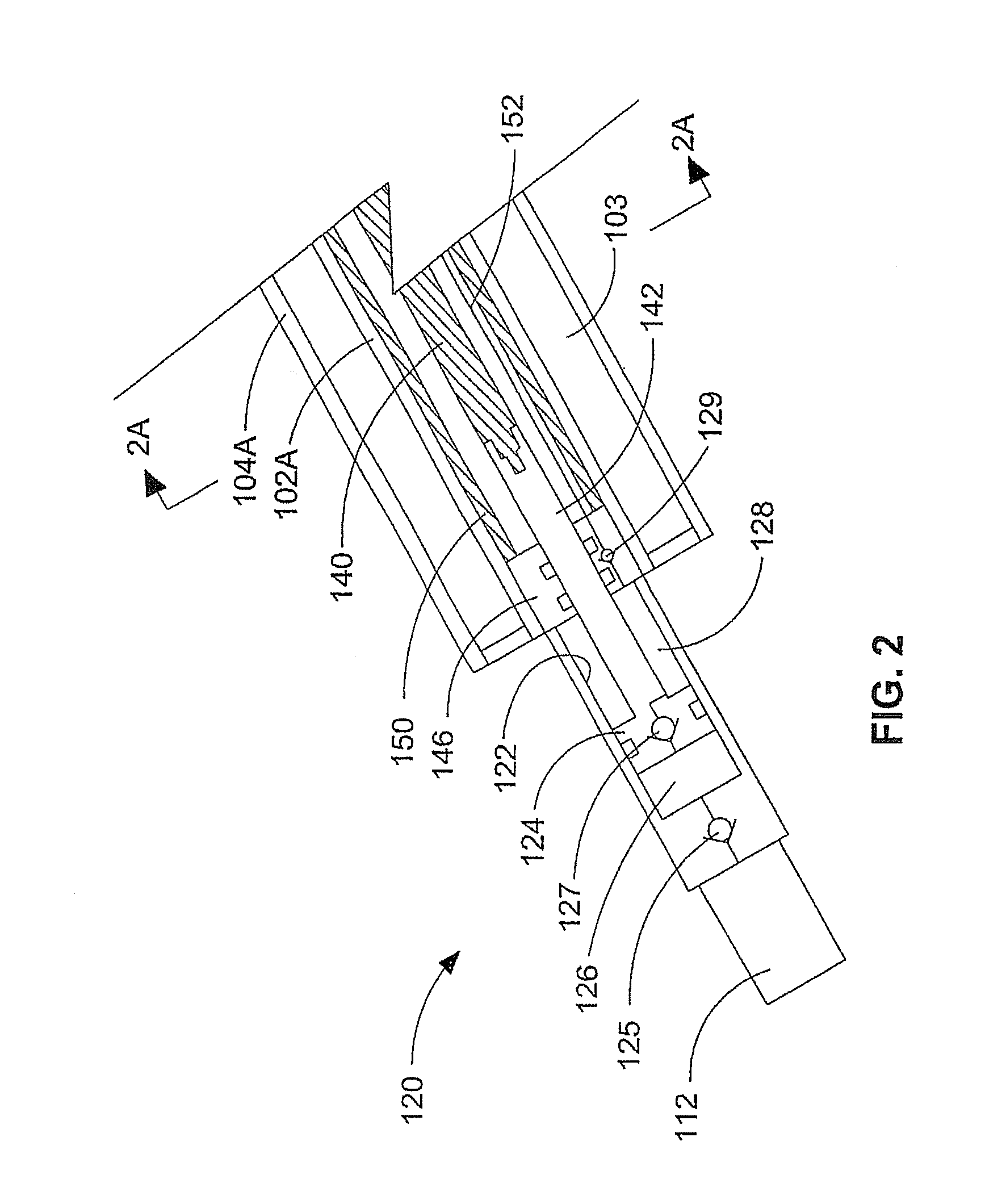
[0031] A double-walled sleeve comprising outer sleeve 104A and inner sleeve 102A extends va...


PUM


Abstract

The apparatus comprises a double walled vacuum insulated vessel defining a cryogen space for holding a cryogenic fluid, a pump assembly comprising a pump with a suction inlet disposed within the cryogen space, and at least one elongated member extending from the pump to a drive unit disposed outside the cryogen space. The elongated member comprises an elongated non-metallic section that has a thermal conductivity that is less than that of a structurally equivalent elongated stainless steel member of the same length. In preferred embodiments, the elongated member can be one or both of a drive shaft or a rigid structural member for supporting the pump and holding it in a fixed relationship to the drive unit. The method employs the apparatus to increase hold times for holding cryogenic fluids by reducing heat leak into the cryogen space.

Description

CROSS-REFERENCE TO RELATED APPLICATION(S) [0001] This application is a continuation of International Application No. PCT / CA2004 / 002166, having an international filing date of Dec. 20, 2004, entitled “Apparatus And Method For Holding A Cryogenic Fluid And Removing Same Therefrom With Reduced Heat Leak”. International Application No. PCT / CA2004 / 002166 claimed priority benefits, in turn, from Canadian Patent Application No. 2,454,458 filed Dec. 24, 2003. International Application No. PCT / CA2004 / 02166 is hereby incorporated by reference herein in its entirety.FIELD OF THE INVENTION [0002] The present invention relates to an apparatus and method for holding a cryogenic fluid and removing cryogenic fluid therefrom with reduced heat leak for improved hold times. More particularly, the apparatus comprises a thermally insulated vessel with a pump disposed therein and means for reducing heat leak into the cryogen space through the pump and drive unit assembly. BACKGROUND OF THE INVENTION [000...

Claims


Application Information

Patent Timeline
IPC IPC(8): F25B19/00F17C13/00F17C13/08F17C3/08F17C9/02
CPCF17C3/08F17C9/02F17C2203/0391F17C2203/0629Y02E60/321F17C2223/0161F17C2227/0135F17C2270/0168F17C2221/012F02M21/0221Y02E60/32Y02T10/30Y10S417/901
Inventor BROOK, THOMASHARPER, GREGORY C.LEBLANC, VALERIA-NADIA
Owner WESTPORT FUEL SYST CANADA INC
Why Eureka
Try Eureka