Tubular radiation absorbing device for solar heating applications

a technology of solar heating and radiation absorption device, which is applied in the direction of solar radiation concentration, solar heat collector mounting/support, solar heat collector with working fluid, etc., can solve the problems of increased heat loss, undesirable pressure fluctuations, and reduction of the efficiency of tubular radiation absorption device, and achieves the effect of greater service li

Inactive Publication Date: 2007-02-15
SCHOTT AG
View PDF16 Cites 54 Cited by
  • Summary
  • Abstract
  • Description
  • Claims
  • Application Information

AI Technical Summary

Benefits of technology

[0015] It is an object of the present invention to provide a tubular radiation absorbing device, especially for a parabolic collector in a solar heat collecting apparatus, based on the tubular radiation absorbing device described in EP 0 286 281 A1, but which is characterized by a greater service life.

Problems solved by technology

This pressure increase leads to increased heat losses and a reduction of the efficiency of the tubular radiation absorbing device.
This arrangement has the disadvantage that the bar is in a region, which is exposed to direct radiation.
Since the getter material with a given loading degree or content has a temperature-dependent equilibrium pressure (equilibrium between gas desorption and adsorption), temperature fluctuations of the getter lead to undesirable pressure fluctuations.
A further disadvantage is that cylindrical press blanks are used, which decompose into a powdery state at higher hydrogen content.
The powder distributes itself in the evacuated intervening space during use of the bar and that leads to impairment of the radiation transmission through the tubular jacket.
Local heating of the glass tubular jacket, which can lead to breakage of glass, occurs because of strong heating by the solar radiation.
It is known from experience with solar power plants in California that a failure rate of about 5% occurs because of this problem.
Furthermore a hydrogen window that is arranged on the exterior of the tubular radiation absorbing device is exposed to exterior environmental influences like rain or dirt.
Corrosion occurs because of exposure to rain water, which results in the destruction of the entire hydrogen window.
Also if the tube operator thus fails to uncover the hydrogen window, it can no longer perform its intended function.

Method used


Image

  • Tubular radiation absorbing device for solar heating applications
  • Tubular radiation absorbing device for solar heating applications
  • Tubular radiation absorbing device for solar heating applications

Examples


Embodiment Construction

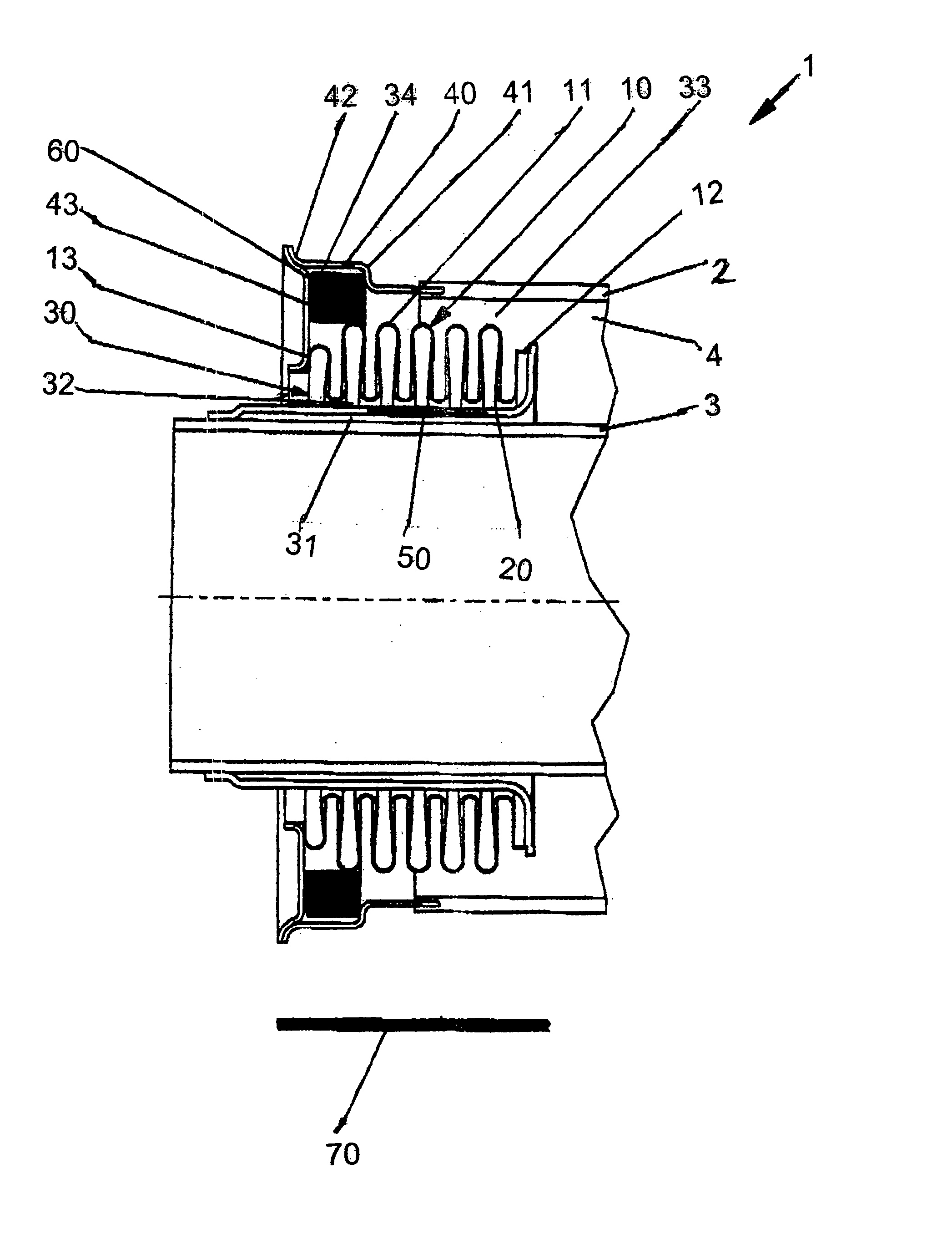
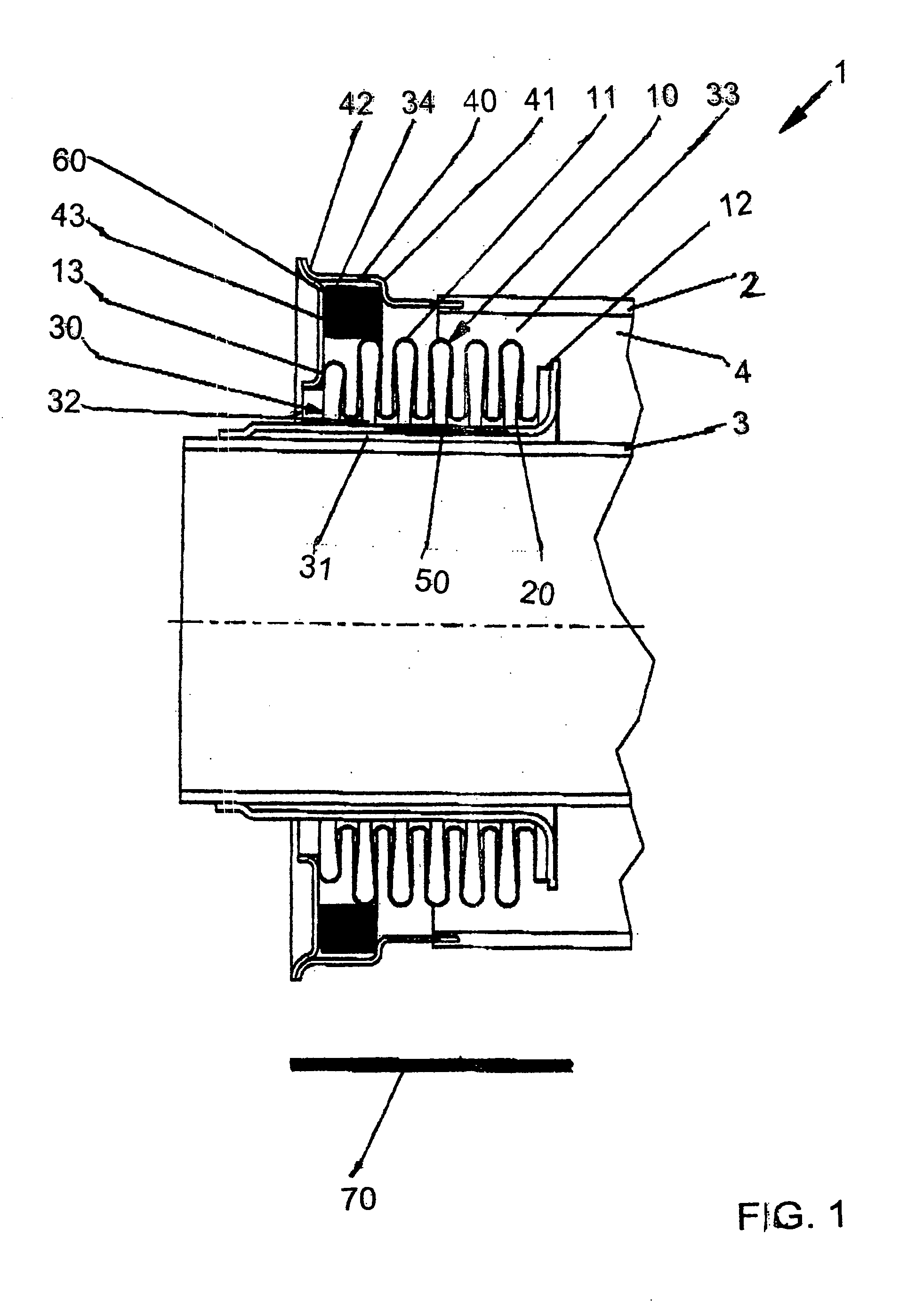
[0035] A longitudinal cross-sectional view through an end portion of the tubular radiation absorbing device 1 is shown in FIG. 1. The tubular radiation absorbing device 1 has a glass tubular jacket 2 and a central metal pipe 3 arranged concentrically in the glass tubular jacket 2. A radiation-selective coating for absorption of the solar radiation is preferably provided on the outside of the central metal pipe 3.

[0036] A glass-metal transitional element 40, which has a circumferential collar 42 pointing toward the outside, is welded with an annular disk 43.

[0037] An expansion compensating device 10 is provided for compensating the differing thermal expansion properties of the central metal pipe 3 and the glass tubular jacket 2. The expansion compensating device 10 comprises a folding bellows 11, which is arranged in a ring-shaped space 4 between the central tube 3 and the tubular jacket 2. The radially interior edge or end of the annular disk 43 is attached with the outer side of ...


PUM


Abstract

A tubular radiation absorbing device (1) designed for a solar heating application is described. The tubular radiation absorbing device has a metal central tube (3) and a glass tubular jacket (2) surrounding the central tube (3). A folding bellows (11) is connected between the central tube (3) and the tubular jacket (2), so that the tubular jacket and the central tube are movable relative to each other. A connecting element (20) connects an inner end of the folding bellows (11) with the central tube (3) and extends from the inner end of the folding bellows (11) through an inner annular space (30) between the folding bellows (11) and the central tube (3). The connecting element includes at least a part of a hydrogen window (50). A getter (6) is arranged in an outer annular space (33) between the folding bellows (11) and the tubular jacket (2).

Description

CROSS-REFERENCE [0001] The invention described and claimed hereinbelow is also described in German Patent Application 10 2005 022 183.1-15, filed May 9, 2005 in Germany, which provides the basis for a claim of priority under 35 U.S.C. 119. BACKGROUND OF THE INVENTION [0002] 1. Field of the Invention [0003] The present invention relates to a tubular radiation absorbing device for solar heating applications, especially for a parabolic collector in a solar heat collecting apparatus, which comprises a central tube, a glass tubular jacket surrounding the central tube so as to form a ring-shaped space between the tubular jacket and the central tube, at least one hydrogen window and an expansion compensating device connecting the central tube and the glass tubular jacket, so that they can move relative to each other in a longitudinal direction. [0004] 2. Description of the Related Art [0005] Tubular radiation absorbing devices or absorber pipes are used in parabolic trough collectors to ut...

Claims


Application Information

Patent Timeline
Patent Type & Authority Applications(United States)
IPC IPC(8): F24J2/46F24S10/70F24S23/74
CPCF24J2/055F24J2/14F24J2/4612Y02E10/45F24J2/4636F24J2002/4681Y02E10/44F24J2/4616F24S10/45F24S23/74F24S40/40F24S40/46F24S40/80F24S2025/6013F24S10/00Y02E10/40
Inventor KUCKELKORN, THOMASBENZ, NIKOLAUS
Owner SCHOTT AG
Why Eureka
Try Eureka