Lighting device for a high-pressure discharge lamp and lighting equipment employing same

a technology of lighting device and high-pressure discharge lamp, which is applied in the direction of electric variable regulation, process and machine control, instruments, etc., can solve the problems of abnormal discharge or discharge in the outer tube, hard turning of high-pressure discharge lamps of this type, energy loss,

Inactive Publication Date: 2007-05-10
MATSUSHITA ELECTRIC WORKS LTD
View PDF8 Cites 4 Cited by
  • Summary
  • Abstract
  • Description
  • Claims
  • Application Information

AI Technical Summary

Benefits of technology

[0013] According to the present invention, when discharge in the outer tube occurs at the end of the life of the high-pressure discharge lamp, the discriminating means for discriminating between normal lighting and abnormal lighting discriminates abnormal lighting, and generation of the high-voltage pulse is stopped within a predetermined period of time in which metallic elements for supporting the arc tube are cooled below

Problems solved by technology

It is known that the high-pressure discharge lamp of this type is hard to be turned on again immediately after it has been turned off, because a high lamp temperature increases the gas pressure inside an arc tube.
Under this condition, an outer tube glass or a threaded plug (base) of the discharge lamp comes to have a high temperature, causing an energy loss.
As a result, when a high-voltage pulse is applied, the discharge starts between the metallic elements for supporting the arc tube, causing abnormal discharge or discharge in the outer tube.
This is caused by deterioration of an electrode on one sid

Method used


Image

  • Lighting device for a high-pressure discharge lamp and lighting equipment employing same
  • Lighting device for a high-pressure discharge lamp and lighting equipment employing same
  • Lighting device for a high-pressure discharge lamp and lighting equipment employing same

Examples


embodiment 1

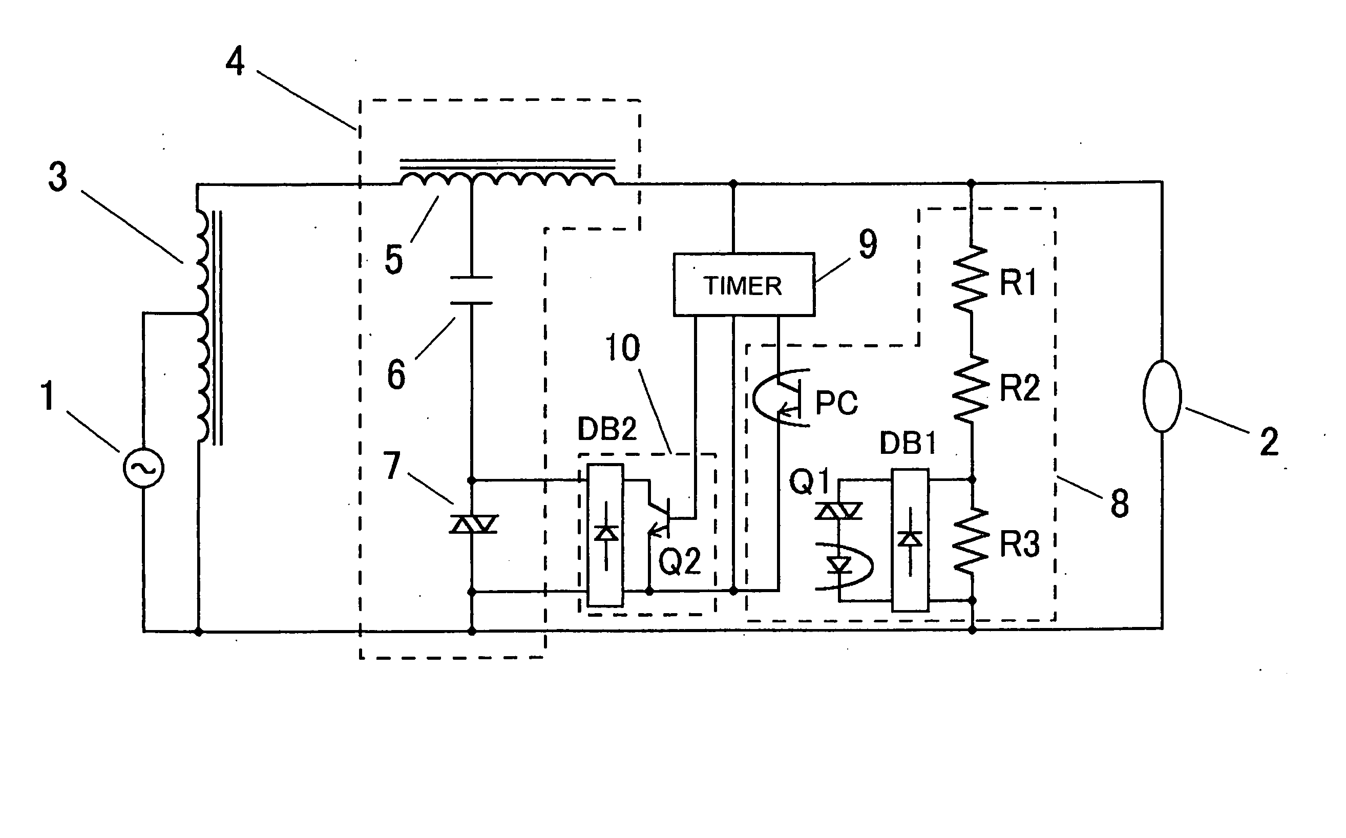
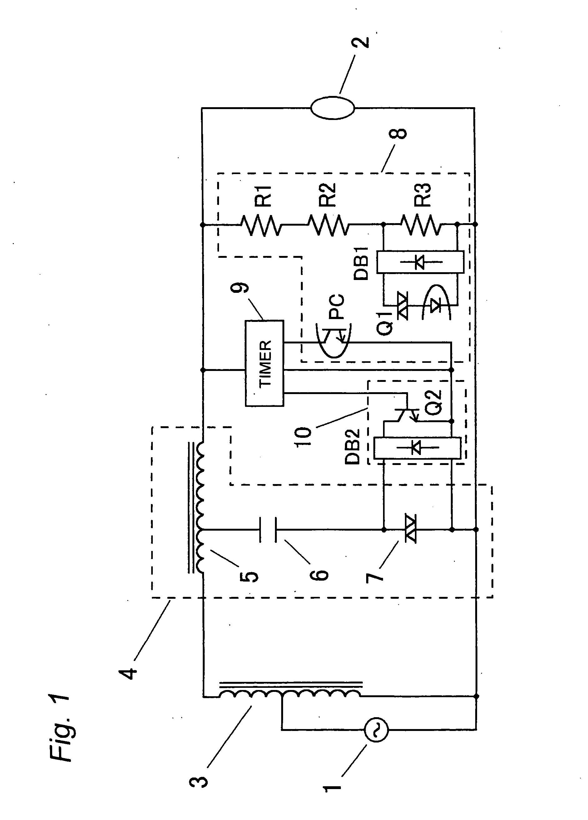
[0022]FIG. 1 depicts a lighting device for a high-pressure discharge lamp according a first embodiment of the present invention. In this embodiment, a lighting discriminating means 8 is connected to opposite ends of a high-pressure discharge lamp 2 to discriminate between normal lighting and abnormal lighting. The lighting discriminating means 8 may be of any construction if it can discriminate abnormal lighting when discharge occurs in an outer tube at the end of the life of the high-pressure discharge lamp 2. In this embodiment, normal lighting and abnormal lighting are discriminated by distinguishing differences in level of a lamp voltage. A series circuit comprised of voltage dividing resistors R1, R2, R3 is connected to the opposite ends of the high-pressure discharge lamp 2 in parallel thereto, and an alternating voltage that is obtained by dividing the lamp voltage is applied to opposite ends of the resistor R3. This alternating voltage is full-wave rectified by a full-wave r...

embodiment 2

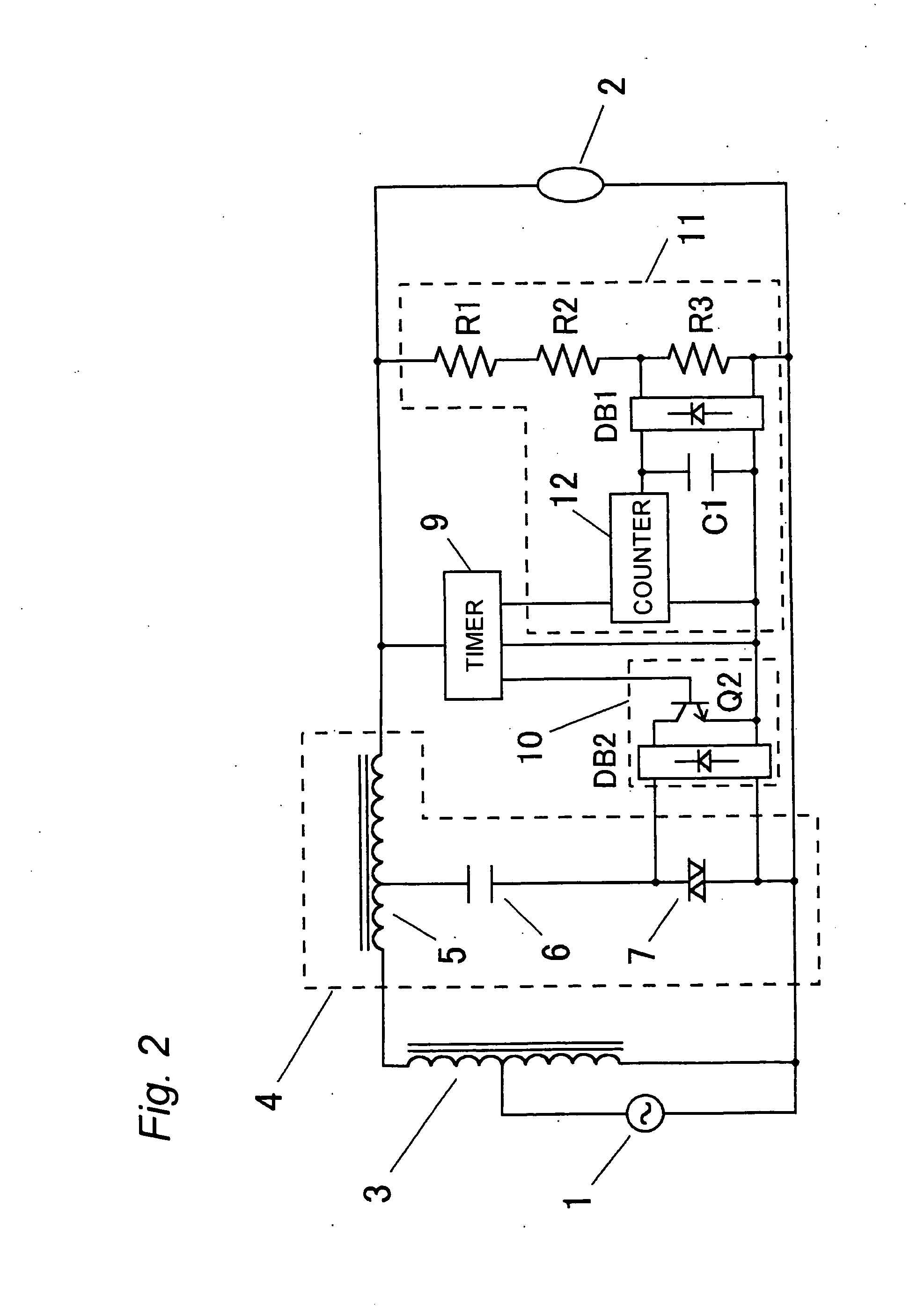
[0029]FIG. 2 depicts a lighting device for a high-pressure discharge lamp according to a second embodiment of the present invention, which includes a ballast 3 including at least a current limiting element and a high-voltage pulse generating circuit 4 for generating a high-voltage pulse. This lighting device is used to light a high-pressure discharge lamp 2 having an outer tube, the interior of which is substantially under vacuum. The lighting device also includes a half-wave discharge detecting means 11 for detecting half-wave discharge of the discharge lamp 2 and a pulse-stop control means 10 for stopping generation of the pulse voltage. When the half-wave discharge detecting means 11 detects half-wave discharge, the pulse-stop control means 10 stops generation of the high-voltage pulse. The lighting device further includes a timer circuit 9 for setting a predetermined period of time. When the half-wave discharge detecting means 11 detects half-wave discharge, generation of the hi...

embodiment 3

[0035]FIG. 4 depicts a lighting device for a high-pressure discharge lamp according to a third embodiment of the present invention, which includes a ballast 3 including at least a current limiting element and a high-voltage pulse generating circuit 4 for generating a high-voltage pulse. This lighting device is used to light a high-pressure discharge lamp 2 having an outer tube, the interior of which is substantially under vacuum. The lighting device also includes a timer circuit 9 for setting a predetermined period of time, a return type temperature detecting and cutoff means 13 for detecting an abnormal temperature rise to thereby cut off power supply to the discharge lamp, and cutoff detecting means 8a, 8b for detecting such cutoff. When the cutoff is detected by the cutoff detecting means 8a, 8b, generation of the high-voltage pulse is stopped within the period of time set by the timer circuit 9.

[0036] In this embodiment, the temperature of a pulse transformer 5 is monitored by ...


PUM


Abstract

A lighting device for lighting a high-pressure discharge lamp 2 having an outer tube, an interior of which is substantially under vacuum. The lighting device includes a ballast 3 having at least a current limiting element and a high-voltage pulse generating circuit 4 for generating a high-voltage pulse, and also includes a lighting discriminating means 8 for discriminating between lighting and non-lighting of the discharge lamp 2, a timer circuit 9 for setting a predetermined period of time, and a pulse-stop control means 10 for stopping generation of the high-voltage pulse. When the lighting discriminating means 8 discriminates non-lighting after lighting has been discriminated, generation of the high-voltage pulse is stopped within the predetermined period of time set by the timer circuit 9.

Description

TECHNICAL FIELD [0001] The present invention relates to a lighting device for lighting a high-pressure discharge lamp and a lighting equipment employing the same. BACKGROUND ART [0002] Lighting devices of this kind are generally provided with a high-voltage pulse generating circuit that applies a high-voltage pulse to a high-pressure discharge lamp to start the lamp. One example of the lighting devices is depicted in FIG. 5. In this figure, reference numeral 1 denotes an AC power source, reference numeral 2 denotes a high-pressure discharge lamp, reference numeral 3 denotes a ballast, reference numeral 4 denotes a high-voltage pulse generating circuit, reference numeral 5 denotes a pulse transformer, reference numeral 6 denotes a capacitor, and reference numeral 7 denotes a switching element. When the switching element 7 turns from an OFF state to an ON state, a pulse-shaped electric current flows through a primary winding N1 of the pulse transformer 5 via the capacitor 6 and, hence...

Claims


Application Information

Patent Timeline
IPC IPC(8): H05B37/02H05B37/03H05B41/04H05B41/24H05B41/18
CPCH05B37/03H05B41/042H05B41/18H05B47/28H05B47/24
Inventor YUFUKU, AKIRAGORIKI, TAKESHIFUKUMORI, NORIYUKIUKITA, NOBUO
Owner MATSUSHITA ELECTRIC WORKS LTD
Why Eureka
Try Eureka