Medical instrument retainer assembly and method of making the retainer

a technology of medical instruments and retainers, which is applied in the field of retainers, can solve the problems of not meeting the new safety requirements proposed by the fda to ensure the freeness of medical trays and their contents, tedious and unwound tasks, and various small parts being misplaced or lost while being processed, so as to prevent the infiltration of bacteria, reduce the possibility of bacterial infiltration thereon, and reduce the cost of production

Inactive Publication Date: 2007-06-14
SYMMETRY MEDICAL MFG INC
View PDF19 Cites 7 Cited by
  • Summary
  • Abstract
  • Description
  • Claims
  • Application Information

AI Technical Summary

Benefits of technology

[0022] As will be described in more detail later, the holding portion of the retainer may be in the form of an elongated slotted blade designed to engage around or receive the medical instruments or it may be in the form of a fence or post positioned to corral instruments placed in the container. In each case, the holding and support portions of the retainer are intimately bonded together to minimize any possibility of bacterial in-growth thereon.
[0023] In a preferred embodiment of the invention, the retainer has an integral seal at each anchoring point thereof which, when the retainer is anchored to the container wall, surrounds the fastener at the corresponding anchoring point thus preventing in-growth of bacteria between the retainer and the container wall at that anchoring point. If a particular retainer has more than one anchoring point, the retainer is preferably shaped SO that its anchoring points extend below the remainder of the retainer so that when the retainer is

Problems solved by technology

Although these prior retainer assemblies perform their instrument retaining function satisfactorily, they may not pass new safety requirements being proposed by the FDA to ensure that medical trays and their contents are fr

Method used


Image

  • Medical instrument retainer assembly and method of making the retainer
  • Medical instrument retainer assembly and method of making the retainer
  • Medical instrument retainer assembly and method of making the retainer

Examples


Embodiment Construction

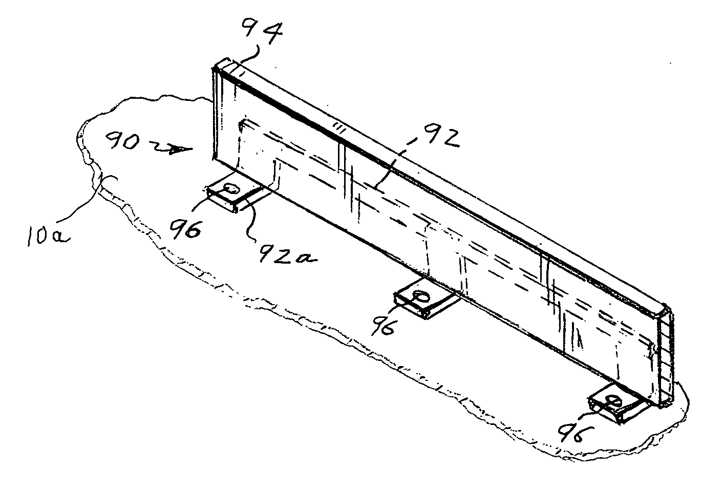
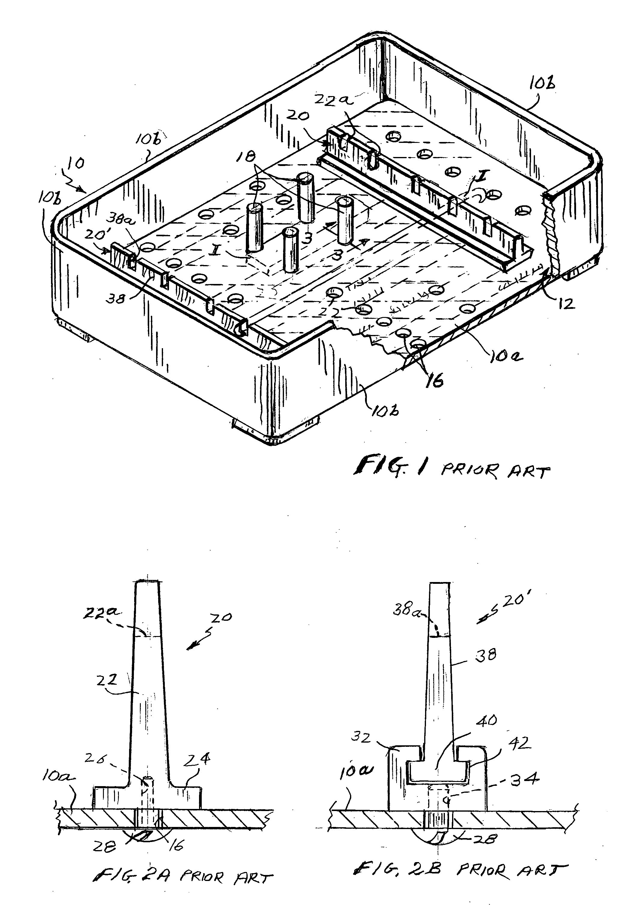
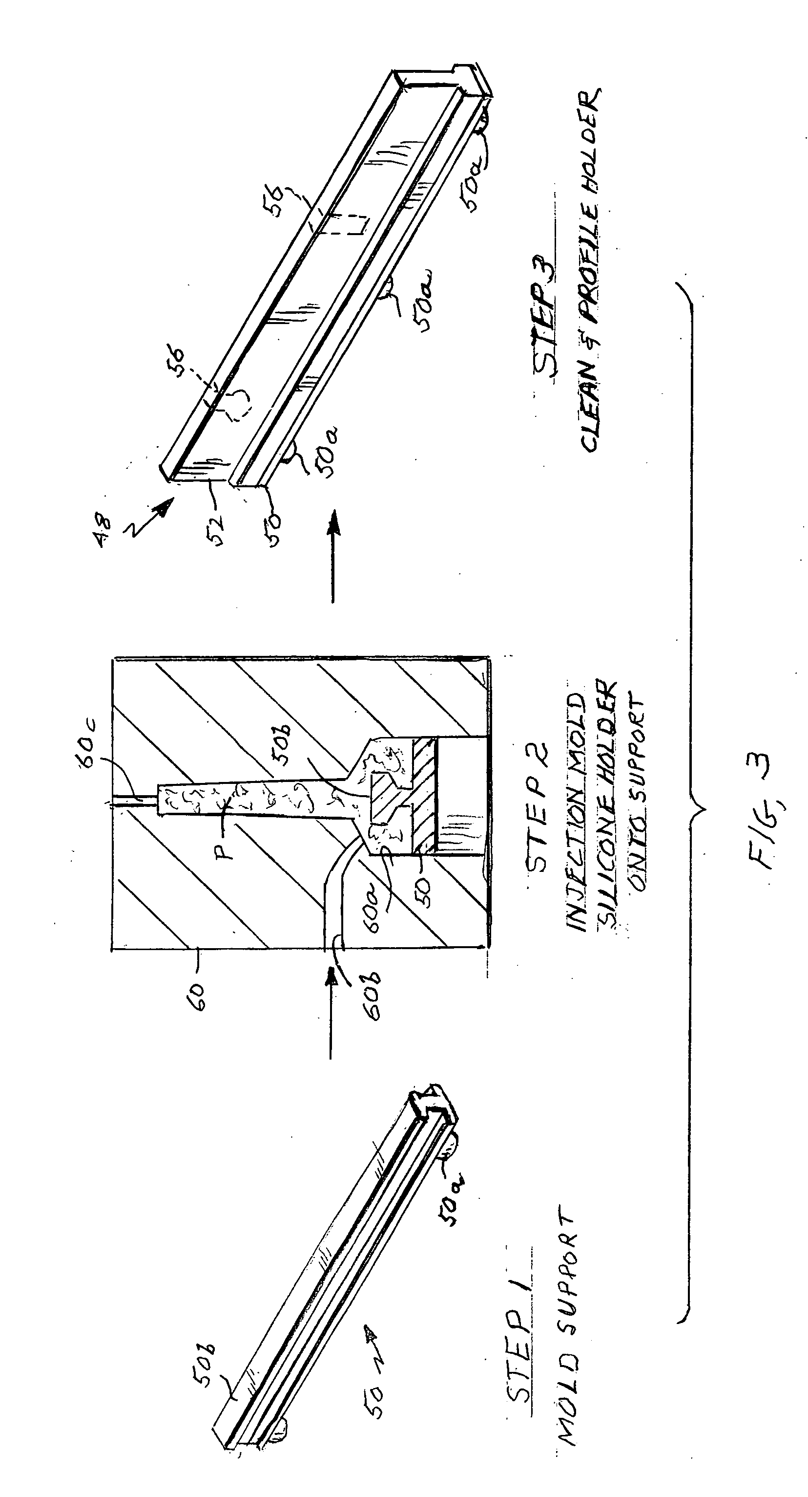
[0034] Referring to FIGS. 4A and 4B and the right hand side of FIG. 3, my improved retainer shown generally at 48 comprises a rigid support portion 50 in the form of an elongated beam and an upstanding flexible resilient blade-like instrument holding portion indicated at 52 which is intimately bonded to support portion 50. The support portion includes one or more legs 50a each of which extends below portion 50 per se to provide an anchoring point. As best seen in FIGS. 4A and 4B, each leg 50a is formed with a threaded passage 54 which extends in from the lower end of the leg for anchoring the retainer to the wall of a container such as the bottom wall 10a of the medical tray illustrated in FIG. 1. For this, each leg 50a is located on base portion 50 so that it can be placed in register with a hole 16 in tray wall 10a. This enables a fastener 28 to be inserted from below the tray through that registering hole and screwed into the passage 54 in the corresponding leg 50a. Of course, if...


PUM

PropertyMeasurementUnit
Pressureaaaaaaaaaa
Flexibilityaaaaaaaaaa

Abstract

A retainer assembly for retaining a medical device in a container having a perforated wall includes a retainer with a rigid support portion having at least one leg and a flexible, resilient instrument holding portion intimately bonded to the support portion so that the retainer is devoid of cracks and crevices between said portions. Each leg has a free end and an axial passage extending into the leg from that end so that the retainer may be positioned on the container wall with each opening in register with a perforation therein. A fastener extends into the passage of each leg and the underlying perforation from below the wall to anchor each leg to the wall under pressure thereby providing a seal between each leg and the wall. Various retainer embodiments and a method for making same are also disclosed.

Description

BACKGROUND OF THE INVENTION [0001] This invention relates to a retainer assembly for retaining medical instruments. It relates especially to a retainer assembly capable of holding medical instruments at fixed positions in a tray or other container while maintaining sterile conditions within the container. [0002] There exists in the prior art various retainers and accessories for fixing the positions of articles of one kind or another. These include hooks, pegs, clips, brackets, etc. Such retainers may be used in a wide variety of applications. For example, they are commonly used in the medical field to fix the positions of various surgical instruments, devices and prostheses while those articles are being transported, sterilized and processed in one way or another. Accordingly, we will describe the invention in that context. It should be understood, however, that the present invention has application in other fields is besides the medical field. [0003] Medical instruments are often ...

Claims


Application Information

Patent Timeline
IPC IPC(8): A61L2/26B29C45/14
CPCA61B19/0256A61B19/0271A61B2019/0258A61L2/26A61L2202/24A61B50/22A61B50/20A61B50/33
Inventor RILEY, EDWARD D.
Owner SYMMETRY MEDICAL MFG INC
Why Eureka
Try Eureka