Pump system for negative pressure wound therapy

a pressure pump and negative pressure technology, applied in the field of wound treatment, can solve the problems of loss of suction to the wound, leakage or blockage of the system, and the airtight seal did not provide any warning if the system developed a leakage or blockage, so as to reduce the likelihood of an erroneous indication of a full canister, prevent the drying of wound exudate, and reduce the tendency of condensate droplets to form.

Active Publication Date: 2010-12-28
PAUL HARTMANN AG
View PDF107 Cites 213 Cited by
  • Summary
  • Abstract
  • Description
  • Claims
  • Application Information

AI Technical Summary

Benefits of technology

[0017]For safety and redundancy, the pump unit has a pressure transducer and a pressure controller that can operate independently from the flow monitor. The pressure controller may use solid state circuitry or may be controlled by a microprocessor or may be a simple mechanical-type device. A user-operable pressure selector enables a user to select a negative pressure pump output within a range of negative pressure setpoints. The pressure controller controls the operation of the pump to maintain the pressure sensed by the pressure transducer between upper and lower limits around the selected setpoint pressure.
[0030]By locating the vent in the conduit close to the wound dressing, the reference airflow also serves to purge the conduit of fluids and other wound exudates. The purging effect minimizes the likelihood of reflux of contaminated fluid back into the wound, and the risk of infection attendant to such reflux. Since the fluid does not reside in the conduit for an extended time, the purge effect also reduces the likelihood of blood clotting in the line. The pump system may also provide a pressure pulse generator to clear the collection line of serial slugs of fluid if a reduction in flow is detected.

Problems solved by technology

Loss of suction to the wound can result if leaks or blockages occur in the system.
This initial check for an airtight seal did not, however, provide any warning if the system developed a leak or if blockage occurred in the collection circuit after hours of use.
The adhesive seal around the suction tube or other tubes which run under the edge of the wound cover in these prior wound dressings is vulnerable to cracking and breaching the airtight seal, creating air leakage into the cover.
While these newer tube attachment devices provide more seal integrity, there is still the potential for breach of the airtight seals due to external causes such as patient movement in bed.
Another potential blockage is kinking or crimping of the suction line itself.
The suction source may also be inadvertently turned off, a line may be inadvertently clamped, or the suction regulator may be misadjusted after the dressing is applied.
Since suction wound dressings are intended to last for long periods without changing, usually 24 hours or greater, a leak or blockage could develop unnoticed and not be detected for a duration sufficient to negate the beneficial healing effect of suction as well as increase the risk of infection.
None of the devices, however, provides a comprehensive and reliable monitoring of system operation, nor cover the full range of fault possibilities with leakage or blockage.
In doing so, they consider the impracticality of locating expensive pressure transducers in any of the system components that should be single-use disposable items due to contamination by body fluids.
However, such water droplets can potentially interfere with the proper functioning of a flow monitor in the system, and may further increase the likelihood of contamination in the system.
Conversely, the inventors considered that at other times, the system is not saturated and drying of wound exudates may occur in the system conduit, causing or aggravating blockages.

Method used


Image

  • Pump system for negative pressure wound therapy
  • Pump system for negative pressure wound therapy
  • Pump system for negative pressure wound therapy

Examples


Embodiment Construction

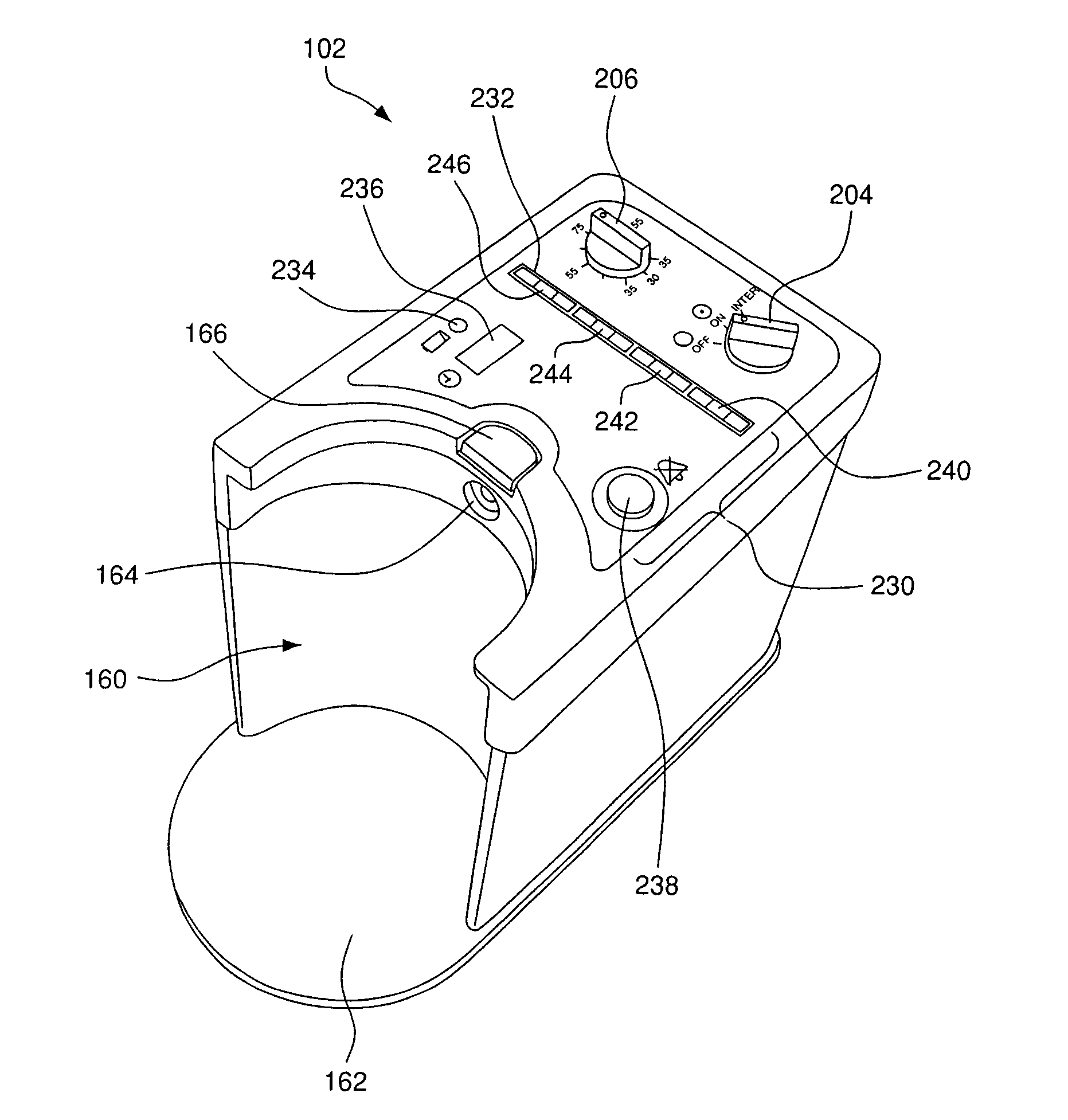
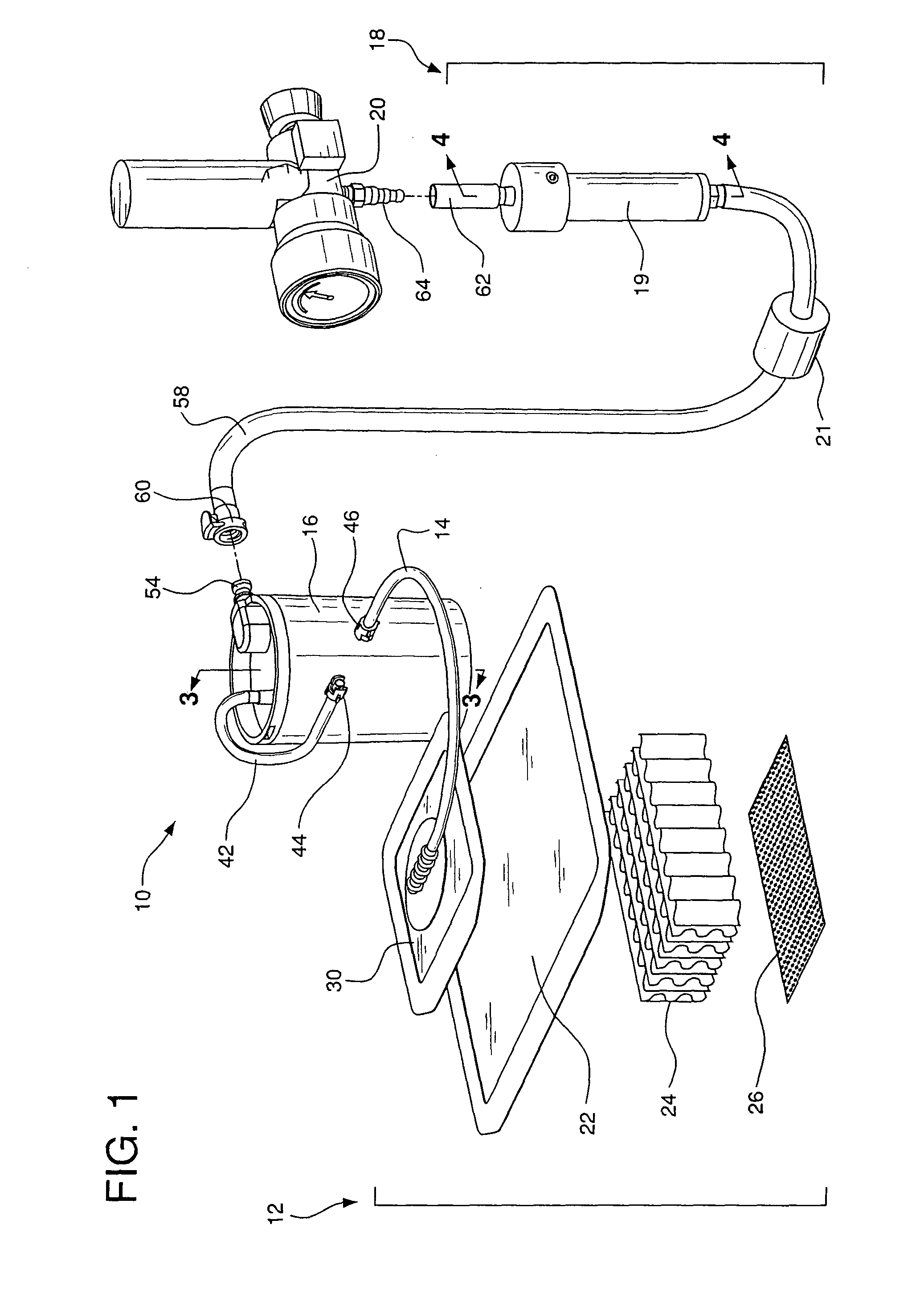
[0047]FIG. 1 shows an embodiment of a system (10) for negative pressure (suction) wound therapy. The system (10) includes a wound dressing (12), a flow monitoring device (18), and a suction regulator (20) for regulating vacuum from a stationary suction source. FIG. 5A shows an alternate embodiment of a system (10) for negative pressure wound therapy where a portable suction pump unit (102) is used in place of the suction regulator (20) and the stationary suction source.

Wound Dressing

[0048]The wound dressing (12) typically includes a primary wound cover (22) and wound packing material (24), and may include a special wound contact layer (26). A suction tube (14) communicates with the wound packing material (24) by running under the edge of the wound cover (22), by extending through the wound cover (22), or by terminating outside of the wound cover (22) and communicating with a nozzle or slot in the wound cover (22). Various wound dressings (12) may be used comprising a wide variety of...


PUM


Abstract

A pump system for applying negative pressure to a wound, including a flow monitor capable of detecting a deviation from a reference airflow rate provided by a controlled leak to determine whether the system is operating normally or abnormally, and a flow status annunciator to indicate a normal operating condition or whether an abnormal condition is a leak or an occluded line in the system. The pump system further includes a pressure controller for regulating operation of a pump to control pressure in the system at a range around a user-selected setpoint. The pump system may also include a waste collector and a level sensor for detecting when the collector is full.

Description

REFERENCE TO RELATED APPLICATIONS[0001]This application is a continuation in part of U.S. patent application Ser. No. 11 / 268,212 which was filed on Nov. 7, 2005 and which claims priority of U.S. Provisional Application No. 60 / 699,218, filed Jul. 14, 2005. This application also claims priority of U.S. Provisional Application No. 60 / 792,187 filed Apr. 14, 2006, and of U.S. Provisional Application No. 60 / 847,221, filed Sep. 26, 2006.FIELD OF THE INVENTION[0002]The invention relates to the general field of wound treatment, and to the more specific field of devices for wound drainage and treatment with suction.BACKGROUND OF THE INVENTION[0003]It is well known to treat wounds by applying suction under airtight wound covers. The suction can be used to aspirate wound exudate and other liquids from the wound and / or the wound packing materials, and the suction can be applied as a healing modality for its well known antiseptic and tissue regeneration effects.[0004]A primary concern in using su...

Claims


Application Information

Patent Timeline
Patent Type & Authority Patents(United States)
IPC IPC(8): A61M1/00A61H7/00A61F13/00A61M27/00
CPCA61M1/0031A61M1/0088G01F1/22G01F1/28A61M1/0029A61M1/0096A61M1/0084A61M2205/3331A61M2205/3344A61M2205/3382A61M2205/15A61M2205/3334A61M2205/6081A61M1/734A61M1/74A61M1/80A61M1/85A61M1/882A61M2205/42A61M1/982A61M1/96A61M1/964A61M1/966
Inventor KARPOWICZ, JOHNRADL, CHRISTOPHER L.KLOCEK, KEVIN P.BOEHRINGER, JOHN R.NORTON, DEREKKROPP, ROBERT
Owner PAUL HARTMANN AG
Why Eureka
Try Eureka