Biodegradable stent

a biodegradable, stent technology, applied in the field of medical devices, can solve the problems of affecting the function of the stent, affecting the stent, etc., and achieve the effect of easy passage from the body lumen

Inactive Publication Date: 2007-01-30
ETHICON INC
View PDF44 Cites 196 Cited by
  • Summary
  • Abstract
  • Description
  • Claims
  • Application Information

AI Technical Summary

Benefits of technology

[0012]It is an object of the present invention to provide a stent for insertion into a body lumen which is manufactured from biodegradable polymers, and which is easily passed from the body lumen after a specific therapeutic period of time.
[0013]It is a further object of the present invention to provide a biodegradable polymeric composition that can be used to make such temporary stents, and that would degrade, breakdown and pass out of the body lumen causing little or no irritation, obstruction, pain and discomfort without being substantially absorbed in the body.
[0019]The inner core typically degrades by hydrolysis and breaks down at a faster rate than the outer layer with exposure to body fluids. The inner core breaks down into small granular particles that are removed easily by the body fluids. The outer layer degrades or erodes into a fibrillar morphological structure. The faster degrading core, after sufficient in vivo exposure, possesses little or no mechanical integrity and is slowly removed, reducing the stent cross-section from a solid to a soft structure that increasingly appears to be hollow. With hydrolytic exposure, the progressively degrading stent can readily pass out of the body lumen, thereby minimizing the possibility of causing obstruction, pain or discomfort. Both the inner core and outer shell although degradable, do not bio-absorb and their degradation products are passed through and out of the body lumen. In one embodiment of the present invention, the device is rendered soft and pliable in vivo, thereby allowing it to easily pass out of the lumen in substantially a unitary piece. In another embodiment, the device not only is rendered soft and pliable, it breaks down into smaller discrete non-occluding pieces that pass out of the lumen.

Problems solved by technology

However, there are several disadvantages that may be associated with the use of metal stents.
Such stents are known to cause irritation to the surrounding tissues in a lumen.
Also, since metals are typically much harder and stiffer than the surrounding tissues in a lumen, this may result in an anatomical or physiological mismatch, thereby damaging tissue or eliciting unwanted biologic responses.
Although permanent metal stents are designed to be implanted for an indefinite period of time, it is sometimes necessary to remove permanent metal stents.
Regardless of whether the metal stent is categorized as permanent or temporary, if the stent has been encapsulated, epithelialized, etc., the surgical removal of the stent will resultingly cause undesirable pain and discomfort to the patient and possibly additional trauma to the lumen tissue.
In addition to the pain and discomfort, the patient must be subjected to an additional time consuming and complicated surgical procedure with the attendant risks of surgery, in order to remove the metal stent.
However, there are disadvantages known to be associated with the use of bioabsorbable or biodegradable stents.
The disadvantages arise from the limitation of the material from which the stent is made.
One of the problems associated with the current stents is that the materials break down too quickly.
This improper breakdown or degradation of a stent into large, rigid fragments in the interior of a lumen, such as the urethra, may cause obstruction to normal flow, such as voiding, thereby interfering with the primary purpose of the stent in providing lumen patency.
Alternatively, they take a long time to breakdown and stay in the target lumen for a considerable period of time after their therapeutic use has been accomplished.
There is thus a long-term risk associated with these materials to form stones when implanted in a urine environment, for example, the urethra.

Method used


Image

  • Biodegradable stent
  • Biodegradable stent
  • Biodegradable stent

Examples


example 1

[0081]A material blend was prepared for use in manufacturing the inner core and outer layer of a fiber useful to wind into a stent of the present invention. The use of this material in fiber formation is described in Example 2.

[0082]The outer shell layer was constituted from a blend of 60 wt % of a first random copolymer containing 90 mole % of polymerized glycolide and 10 mole % polymerized lactide and 40 wt % of a second copolymer containing 85 mole % polymerized lactide and 15 mole % polymerized glycolide. The inherent viscosity of the first copolymer containing 90 mole % polymerized glycolide and 10 mole % polymerized lactide, to be henceforth referred to as 90 / 10 glycolide / lactide copolymer, was 1.4 dL / g as determined in HFIP (hexafluroisopropanol) at 25° C. at a concentration of 0.1 g / dL. The inherent viscosity of the second copolymer containing 85 mole % polymerized lactide and 15 mole % polymerized glycolide, to be henceforth 85 / 15 lactide / glycolide copolymer, was 2.1 dL / g a...

example 2

[0084]The fabrication method for coextruded fibers with round cross-sections follows. The material used in the inner core and outer layer shell has been described in Example 1 above. The outer shell layer was made from a blend of 60 wt % 90 / 10 glycolide / lactide copolymer and 40 wt % of 85 / 15 lactide / glycolide copolymer. The inner layer was made from a blend of 95 wt % of 75 / 25 glycolide / caprolactone segmented block copolymer and 5 wt. % Barium Sulfate. Also the in vitro tensile testing of the fibers is presented and compared to coextruded fibers that have only the 90 / 10 glycolide / lactide copolymer.

[0085]The fibers were co-extruded using two single screw extruders. Both screws had compression ratios of 3:1 and an l / D of 25:1. A 1″ horizontal extruder was used for outer shell layer and ⅝″ vertical extruder was used for the inner core. A concentric two-layer feed-block was used to feed the two material stream into a single orifice die from which the extrudate is fed to a water trough f...

example 3

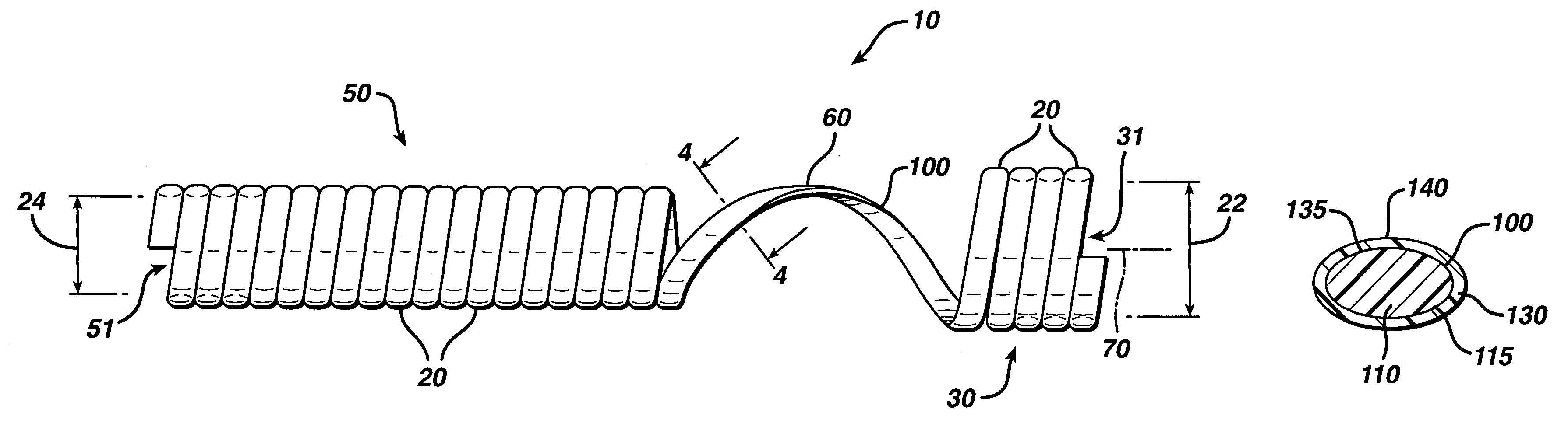
[0090]A process used to convert fibers having an oval or elliptical cross-section into stents is described in this example. A stent with single helix structure was formed from a single oval fiber. Coextruded fibers containing materials made in Example 1 were considered for the shell and core of the oval fiber.

[0091]The process to make oval coextruded fibers is described first. The material used in the outer core and inner shell has been described in Example 1. The outer shell layer was made from a blend 60 wt % of 90 / 10 glycolide / lactide copolymer and 40 wt % of 85 / 15 lactide / glycolide copolymer. The inner layer was made from a blend of 95 wt % of 75 / 25 glycolide / caprolactone segmented block copolymer and 5 wt. % barium sulfate.

[0092]The oval fibers were coextruded using two single screw extruders. Both screws had compression ratios of 3:1 and a L / D of 25:1. A 1″ horizontal extruder was used for outer shell layer and ⅝″ vertical extruder was used for the inner core. A concentric two...


PUM

PropertyMeasurementUnit
weight percentaaaaaaaaaa

Abstract

The present invention is directed to stents that are formed into a helical structure having a plurality of coils, a longitudinal axis, an internal longitudinal passage, a distal section and a proximal section having different diameters; where the structure is made from a fiber having a cross-section and including an inner core having an exterior surface made from a biodegradable polymer having a first degradation rate and an outer section made from a blend of a first biodegradable polymer component and a second biodegradable polymer component covering the exterior surface of the inner core and having a second degradation rate; where the second degradation rate is lower than the first degradation rate.

Description

[0001]This application is a continuation-in-part which claims the benefit of non-provisional pending U.S. patent application Ser. No. 10 / 256,942, filed Sep. 27, 2002, which is a continuation of U.S. patent application Ser. No. 09 / 933,059, filed Aug. 20, 2001, now U.S. Pat. No. 6,537,312, issued Mar. 25, 2003, which is a continuation of U.S. patent application Ser. No. 09 / 470,619, filed Dec. 22, 1999, now U.S. Pat. No. 6,338,739, issued Jan. 15, 2002, which is hereby incorporated by reference herein.FIELD OF THE INVENTION[0002]The field of art to which this invention relates is medical devices, in particular, stent devices made from biodegradable polymers.BACKGROUND OF THE INVENTION[0003]The use of stent medical devices, or other types of endoluminal mechanical support devices, to keep a duct, vessel or other body lumen open in the human body has developed into a primary therapy for lumen stenosis or obstruction. The use of stents in various surgical procedures has quickly become acc...

Claims


Application Information

Patent Timeline
Patent Type & Authority Patents(United States)
IPC IPC(8): A61F2/04A61F2/06A61F2/02A61L31/00A61F2/84A61F2/88A61L31/04A61L31/06A61L31/10A61L31/14
CPCA61F2/88A61L31/041A61L31/06A61L31/10A61L31/14A61L31/148C08L67/04A61F2210/0004
Inventor DATTA, ARINDAMHUXEL, SHAWN THAYERJAMIOLKOWSKI, DENNIS D.LI, YUFUTENHUISEN, KEVOR S.
Owner ETHICON INC
Why Eureka
Try Eureka