Piezoelectric sensor in a living organism for fluid pressure measurement

a technology of fluid pressure measurement and living organisms, applied in the field of pressure sensors, can solve problems such as affecting the measurement results

Inactive Publication Date: 2005-05-03
ST JUDE MEDICAL
View PDF12 Cites 77 Cited by
  • Summary
  • Abstract
  • Description
  • Claims
  • Application Information

AI Technical Summary

Benefits of technology

[0009]An object of the present invention therefore is to provide a pressure sensor, which is sensi

Problems solved by technology

A general problem with this kind of measurement is to avoid flow generated pressure components, and for the kind of pressure measurement described it is desirable that the sensor is sensitive to pressure variations all around the periphery of the sensor.
None

Method used


Image

  • Piezoelectric sensor in a living organism for fluid pressure measurement
  • Piezoelectric sensor in a living organism for fluid pressure measurement
  • Piezoelectric sensor in a living organism for fluid pressure measurement

Examples


first embodiment

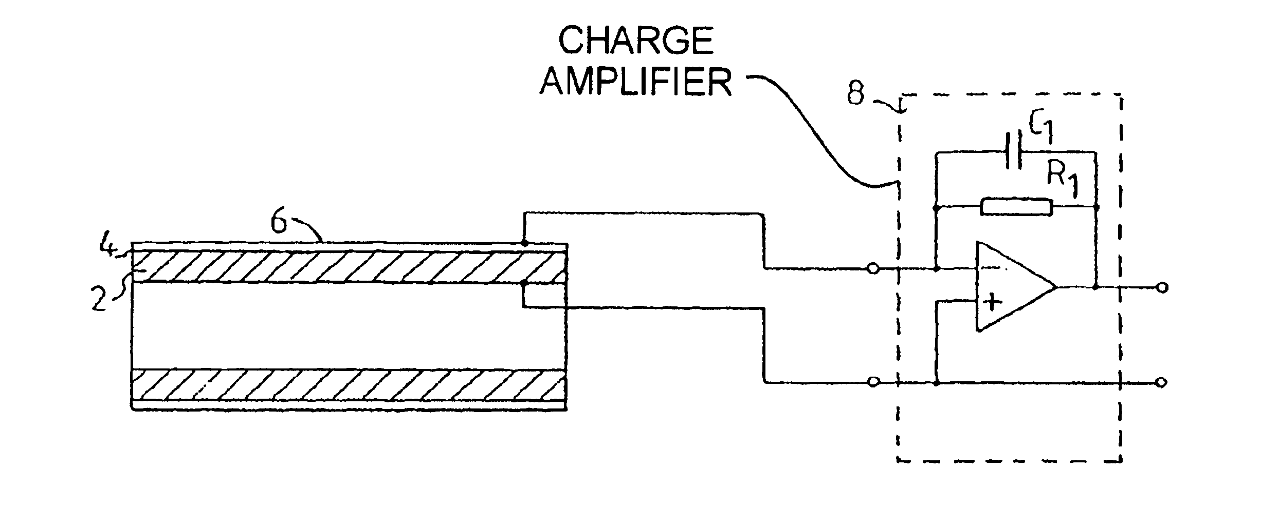
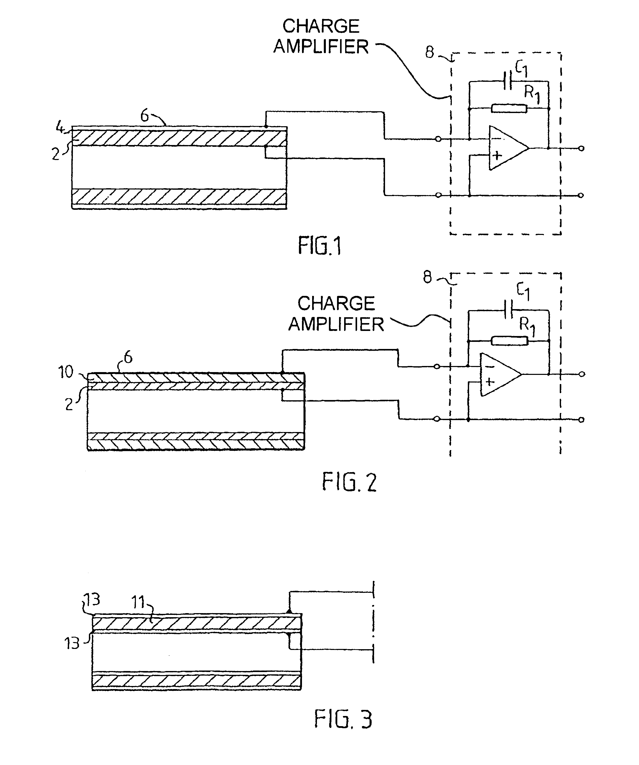
[0024]In FIG. 1 shows a longitudinal section of the sensor according to the invention. This embodiment has a sensing element in the form of a tube 2 which on its outer surface is covered with a layer 4 of a piezoelectric material, preferably a ceramic piezoelectric material. Preferred materials are PZT and potassium-sodium-niobate. The layer may be applied on the tube 2 by sputtering, laser-ablation or any other suitable method. On the outer surface of the piezoelectric layer 4 a layer 6 of a conductive material, e.g. titanium, titanium alloy, titanium nitride, platinum, platinum alloy, carbon, niobium, niobium alloy, tantalum or tantalum alloy is applied in a similar way. In this way the tube 2 and the layer 6 form electrodes which are connected to an amplifier 8 for measuring the charge produced in the piezoelectric layer 4 when it is subject to pressure variations.

[0025]The tube 2 is a rigid tube, that may be placed inside the outer silicon rubber insulation of a pacing lead 18 w...

second embodiment

[0028]FIG. 2 shows the sensor according to the invention having a tube of a piezoelectric material 10 disposed around the inner tube 2 of platinum—iridium alloy, titanium or carbon. Electric contact between these two tubes 2, 10 may be formed for example, with an electrically conducting glue. On the outer surface of the piezoelectric tube 10 a conducting layer 6 is applied as in the embodiment in FIG. 1. Also, like in the previously described embodiment, the tube 2 and the layer 6 form electrodes that are connected to a charge amplifier 8 mounted in a pacemaker for measuring electrical charges generated in the piezoelectric tube, when the tube is subjected to radial pressure variations.

third embodiment

[0029]FIG. 3 shows the sensor element of the sensor according to the invention having a rigid tube 11 of a piezoelectric material with inner and outer electrodes 13, i.e. the supporting structure and the piezoelectric layer are both made of piezo-electric material and may also be made of the same material. In this case the tube is provided with an inner conducting layer as well.

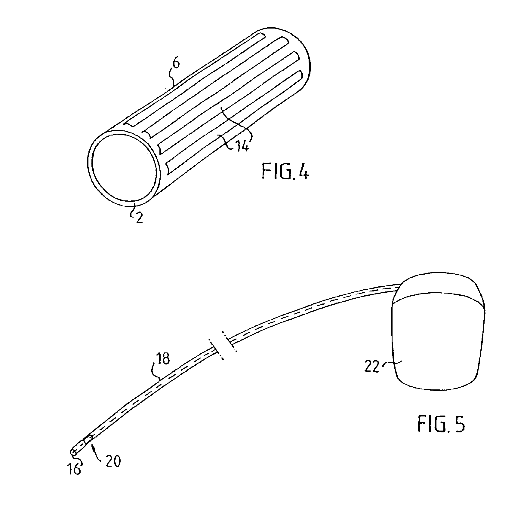
[0030]FIG. 4 shows an embodiment in which the piezoelectric element is formed as longitudinal strips 14 of piezoelectric material distributed around the outer surface of the supporting tube 2 with gaps or spaces respectively between the strips 14.

[0031]As mentioned above an important feature of the sensor according to the invention resides in the fact that it is sensitive to pressure variations all around its periphery. Thus it will operate reliable also if it should happen to be positioned against a heart wall. Since the sensor has an annular or tubular design electric conductors and guide wires can easily b...


PUM


Abstract

A fluid pressure sensor for a lead or catheter intended for placement in a living organism, such as a human heart, includes a rigid annular or tubular supporting structure and a piezoelectric element disposed on at least a portion of the outer surface thereof. The piezoelectric element delivers an electrical signal when subjected to a pressure variation, and exhibits circumferential sensitivity. The rigidity of the sensor is defined to satisfy predetermined criteria to ensure that the sensor, when sensing pressure transferred to the sensor through an on-growth of tissue on the sensor, which is at least 90% of the signal which the sensor would emit without the on-growth.

Description

[0001]This application is a 371 of PCT / SE01 / 02345, filed Oct. 24, 2001.BACKGROUND OF THE INVENTION[0002]1. Field of the Invention[0003]The present invention relates to a pressure sensor for mounting in the distal end portion of a lead or catheter intended to be placed in a living organism, such as the heart of a human being, of the type having a piezoelectric element delivering an electric signal when subjected to a pressure variation.[0004]2. Description of the Prior Art[0005]With the aid of a pressure sensor in the heart, tachycardias, such as fibrillation, can be detected and distinguished. Atrial fibrillation e.g. can be separated from ventricular fibrillation and electrical activity can be separated from mechanical activity. This is of importance for controlling the type of stimulation therapy to be delivered by a heart stimulator.[0006]From the time derivative of the blood pressure, dP / dt, an indication is obtained of the contractility of the heart, which in turn is a measure ...

Claims


Application Information

Patent Timeline
IPC IPC(8): A61B5/0215A61B19/00G01L9/06G01L9/08
CPCA61B5/0215G01L9/08G01L9/06A61B2019/464A61M2025/0002A61B2562/0247A61B2090/064
Inventor KJELLMAN, CHARLOTTELIDMAN, JOHANLJUNGSTROM, KARINNILSSON, KENTH
Owner ST JUDE MEDICAL
Why Eureka
Try Eureka