Crimp sleeve connector having crimp indicator

a technology of crimp sleeve connector and indicator, which is applied in the direction of hose connection, coupling, pipe coupling, etc., can solve the problems of improper connection and wasted tubing, and achieve the effect of being convenient to produce and opera

Inactive Publication Date: 2007-06-14
TRANS MATIC MFG CO INC
View PDF8 Cites 32 Cited by
  • Summary
  • Abstract
  • Description
  • Claims
  • Application Information

AI Technical Summary

Benefits of technology

[0016] The indicator system provides the installer with instant recognition of the state of the crimping of the crimp band. The crimp band indicator of the present invention may be readily attached to the crimp sleeve connector at the manufacturing stage or the crimp band indicator may be attached to a crimp sleeve connector as an after-market indicator. The crimp band indicator of the present invention is also inexpensive to produce and to operate.

Problems solved by technology

Too much overlap of the tube onto the fitting results in wasted tubing whereas too little overlap of the tube onto the fitting risks an improper connection.

Method used


Image

  • Crimp sleeve connector having crimp indicator
  • Crimp sleeve connector having crimp indicator
  • Crimp sleeve connector having crimp indicator

Examples


Embodiment Construction

[0030] In the following figures, the same reference numerals will be used to refer to the same components. In the following description, various operating parameters and components are described for one constructed embodiment. These specific parameters and components are included as examples and are not meant to be limiting.

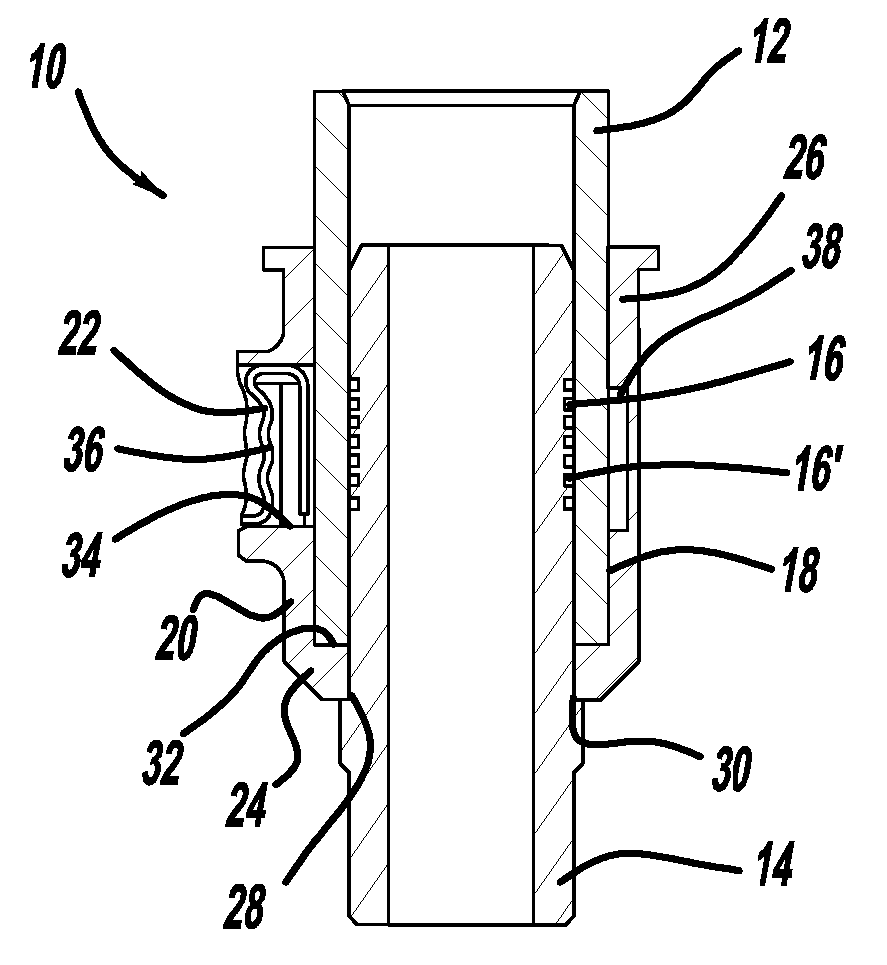
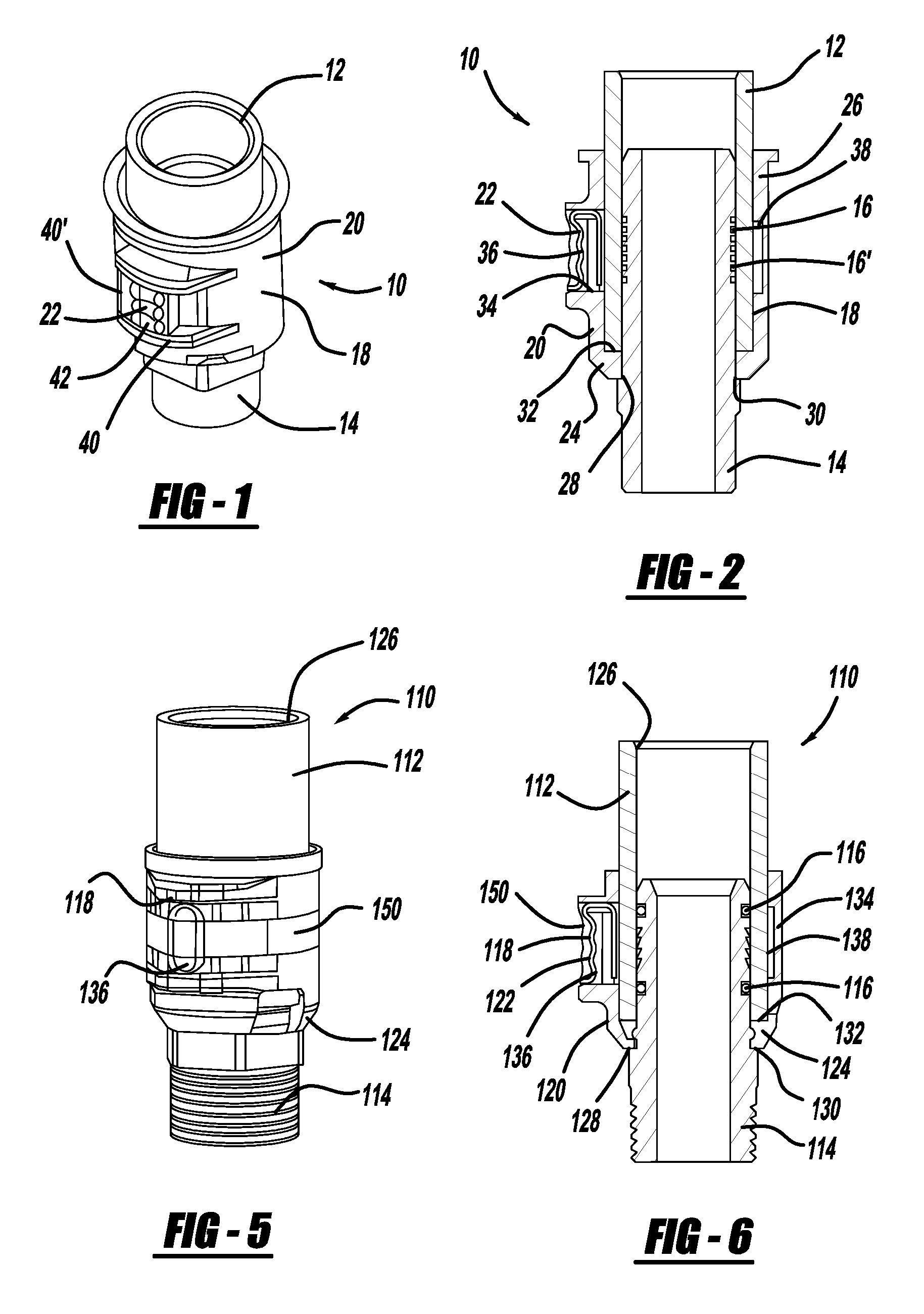
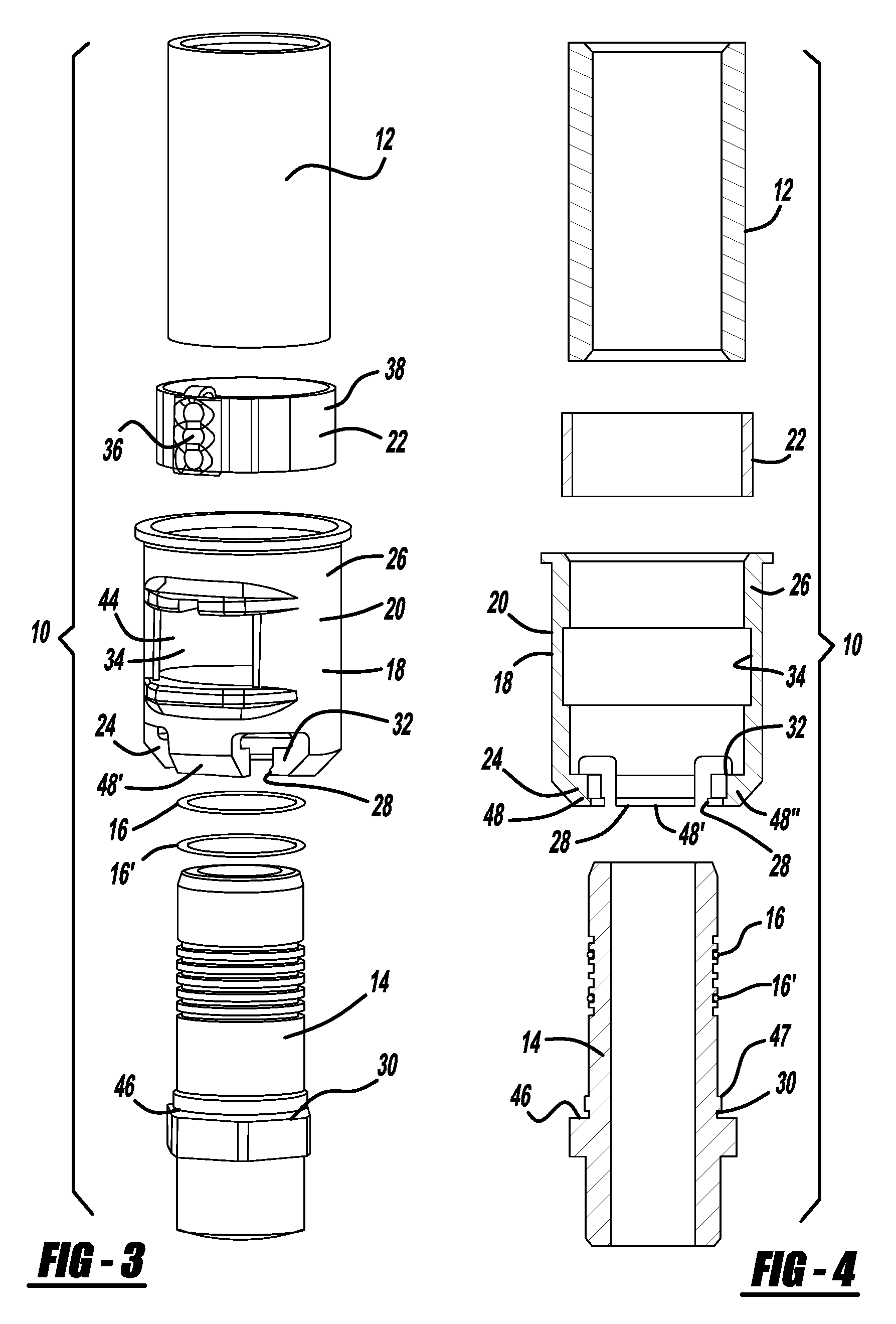
[0031] With reference to FIG. 1, a perspective view of the assembled tube, fitting and crimp sleeve connector, generally illustrated as 10, is shown. It is to be understood that the illustrated size and shape of the assembly 10 is shown for illustrative purposes and is not intended to be limiting. The assembly 10 is illustrated in cross-section in FIG. 2.

[0032] Referring to both FIG. 1 and FIG. 2, the assembly 10 includes a tube 12 that may be composed of a variety of materials including plastic or vinyl. In addition, the tube 12 may have a core composed of a metal, such as aluminum, and have a wrapping of a polymerized material.

[0033] The assembly 10 further ...


PUM


Abstract

A crimp sleeve connector is provided for the secure connection of a tube and a fitting. The crimp sleeve connector is substantially positionable on the fitting and the tube is inserted between the fitting and the crimp sleeve connector. The connector includes a crimp ear which extends through the body of the crimp sleeve connector. At least one o-ring is fitted over the fitting in such a position that when the tube, fitting and crimp sleeve connector are in place the o-ring functions to maintain a fluid-tight seal. An alternative embodiment of the crimp sleeve connector includes a crimp indicator in the form of a band which falls away after crimping, thus allowing visual confirmation that the crimp ear has been crimped.

Description

RELATED APPLICATIONS [0001] This application is a continuation-in-part of U.S. Ser. No. 10 / 921,536, filed Aug. 18, 2004, and claims priority to U.S. Provisional Patent Application Ser. No. 60 / 775,890, filed Feb. 23, 2007, U.S. Provisional Patent Application Ser. No. 60 / 814,112, filed Jun. 16, 2006, and U.S. Provisional Patent Application Ser. No. 60 / 852,162, filed Nov. 17, 2006.TECHNICAL FIELD [0002] The present invention relates generally to sleeve connectors for attaching a tube to a fitting. More particularly, the present invention relates to crimp sleeve connectors that can be crimped to attach a tube to a fitting. The present invention further relates to indicators for use with such crimp sleeve connectors for providing positive confirmation that the connector has been crimped. BACKGROUND OF THE INVENTION [0003] Fluid carrying conduits are used in a variety of environments including building structures such as homes and manufacturing facilities as well as in transportation vehi...

Claims


Application Information

Patent Timeline
Patent Type & Authority Applications(United States)
IPC IPC(8): H01R9/05
CPCF16L13/143F16L33/025F16L2201/10
Inventor POLL, STEVEN ALLENDALESSANDRO, RONALD MARKSIX, RUSSEL CHRISTOPHER
Owner TRANS MATIC MFG CO INC
Why Eureka
Try Eureka