Video surveillance camera

Active Publication Date: 2006-03-16
PELCO INC
View PDF10 Cites 36 Cited by
  • Summary
  • Abstract
  • Description
  • Claims
  • Application Information

AI Technical Summary

Benefits of technology

[0008] Among the many advantages of the present invention is the ability to adjust the back focus of a camera system without twisting or turning the camera lens while still minimizing the number of movable parts. In addition, the present invention allows the position of the lens to be easily adjusted and then securely fastened relative to the camera bo

Problems solved by technology

The first method is not efficient or practical for thermal management of the image sensor.
The second method r

Method used


Image

  • Video surveillance camera
  • Video surveillance camera
  • Video surveillance camera

Examples


Example

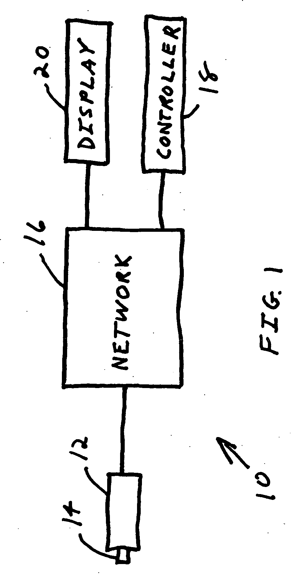
[0016] Referring to FIG. 1, a video surveillance system 10 utilizing the present invention is shown in block diagram form. Video surveillance system 10 comprises a camera 12 having a lens 14. Camera 12 is connected to network 16, which can be a closed network, local area network, or wide area network, such as the Internet. A controller 18 is connected to network 16 to control video surveillance system 10 as is known in the art. The video images captured by camera 12 can be viewed by the user on display 20. Video surveillance system 10 can comprise a plurality of video cameras, video recorders, and other surveillance devices as is known in the art.

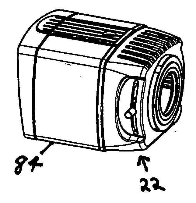
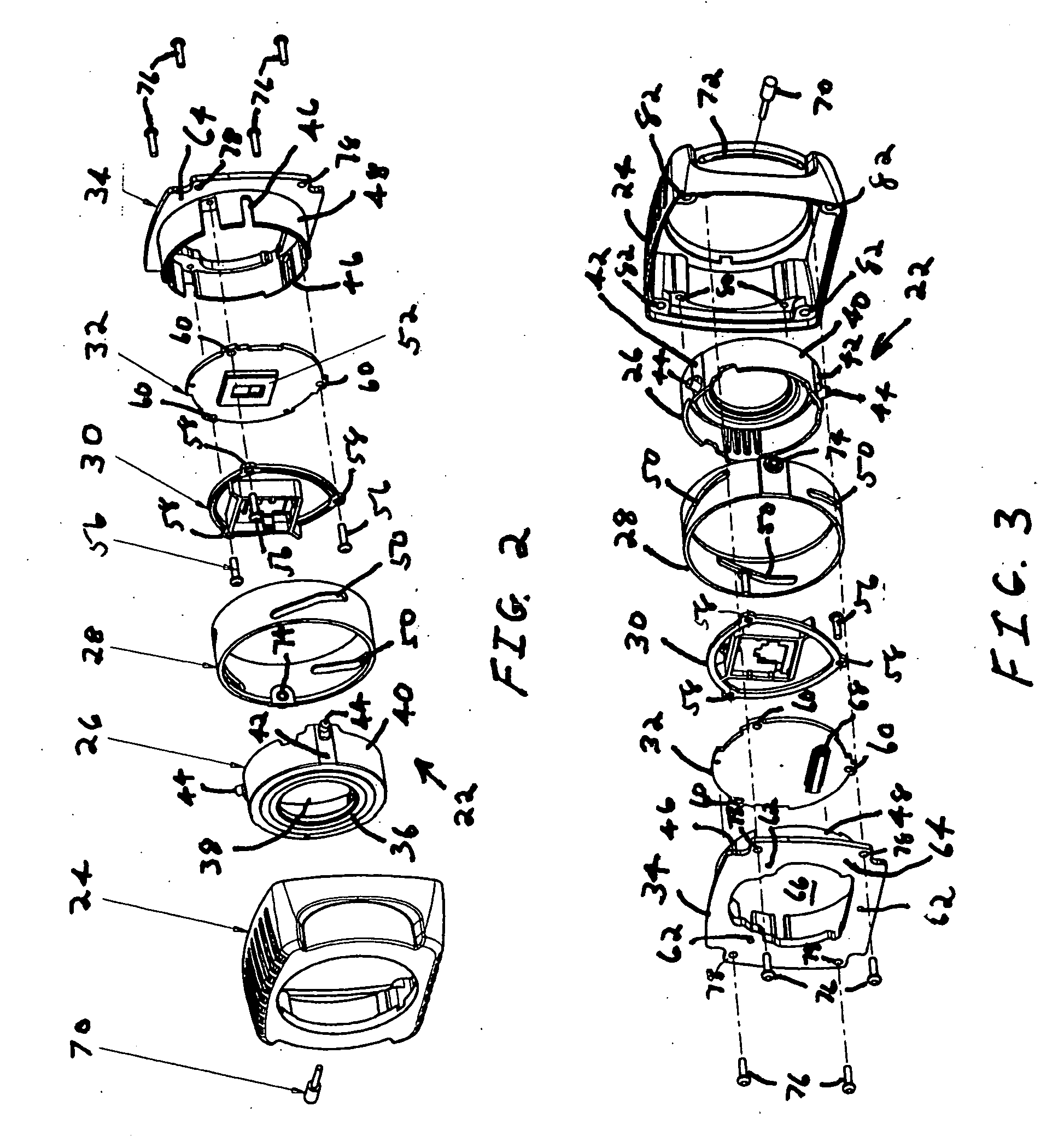
[0017] Referring to FIGS. 2 and 3, a back focus assembly 22 has a housing 24, lens holder 26, adjustment ring 28, filter holder 30, imager board 32, and base 34. Lens holder 26 has a front end 36 with an aperture 38 for receiving commercially available camera lenses and / or lens adaptors (not shown). Lens holder 26 is preferably a single pl...


PUM


Abstract

A video surveillance camera comprising a lens, lens holder, image sensor, base, and ring. The base has a plurality of slots, and the image sensor is mounted on the base. The lens is positioned in the lens holder, which has a plurality of arms with a pin. Each of the arms is positioned so that its respective pin is located in one of the plurality of slots in the base. The ring has a plurality of grooves for engagement with the pins and is rotatably engaged with the base such that rotation of the ring imparts axial movement to the lens relative to the image sensor.

Description

CROSS-REFERENCE TO RELATED APPLICATION [0001] N / A STATEMENT REGARDING FEDERALLY SPONSORED RESEARCH OR DEVELOPMENT [0002] N / A BACKGROUND OF THE INVENTION [0003] The present invention relates to video surveillance cameras and, more particularly, to an assembly for adjusting the back focus of a video surveillance camera. [0004] Video surveillance cameras must be able to provide clear and distinct images since such images may be used for security, evidentiary, identification, or other similar purposes. Present camera systems generally provide for adjustment of the back focus by moving the image sensor forward or backward while the lens stays stationary. Alternatively, for camera systems where the image sensor remains stationary, back focus is accomplished by physically adjusting the linear location of the lens assembly by screwing the lens assembly in and out of the camera body's threaded bushing. The first method is not efficient or practical for thermal management of the image sensor....

Claims


Application Information

Patent Timeline
IPC IPC(8): H04N5/225H04N7/18H04N9/47
CPCH04N5/2254H04N23/55
Inventor POKROVSKY, ALEXLYON, THOMASTEWS, ERIKJOHNSON, MARK J.
Owner PELCO INC
Why Eureka
Try Eureka