Inflation/deflation valve for cargo dunnage

Inactive Publication Date: 2007-09-25
ROBBINS JAMES A
View PDF30 Cites 8 Cited by
  • Summary
  • Abstract
  • Description
  • Claims
  • Application Information

AI Technical Summary

Benefits of technology

[0016]A further object of the present invention is to provide an improved valve assembly which includes a minimized number of operational parts so as to lessen the likelihood of malfunction.
[0017]A still further object of the pr

Problems solved by technology

While cargo is generally loaded as snugly into a vehicle as possible, such as a cargo hold of a truck or rail car, it is frequen

Method used


Image

  • Inflation/deflation valve for cargo dunnage
  • Inflation/deflation valve for cargo dunnage
  • Inflation/deflation valve for cargo dunnage

Examples


Example

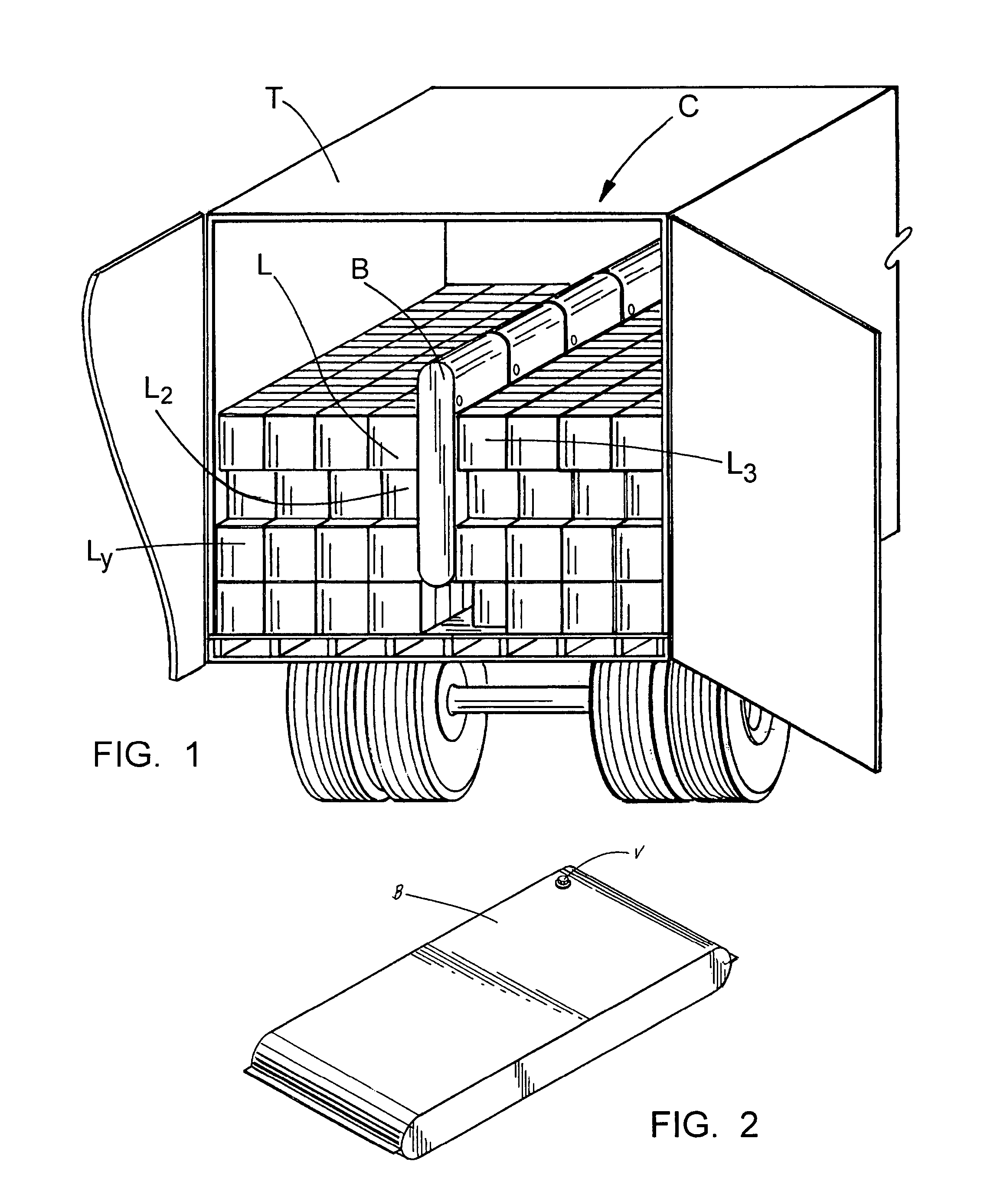
[0030]FIGS. 1 and 2 show generally the application of the dunnage bag in which the present invention has use. FIG. 1 illustrates a bag B disposed in the cargo area C of a truck trailer T intermediate load articles L1, L2, L3, . . . Ly. FIG. 2 generally illustrates a dunnage bag having a valve V for inflation and deflation. Dunnage bags are used principally in long haul transportation of boxed or crated loads. As known in the art, it is important to secure the load against shifting and other movement which might allow the cargo to become damaged. Dunnage bags have become a very useful tool to be placed into openings between adjacent boxes or crates.

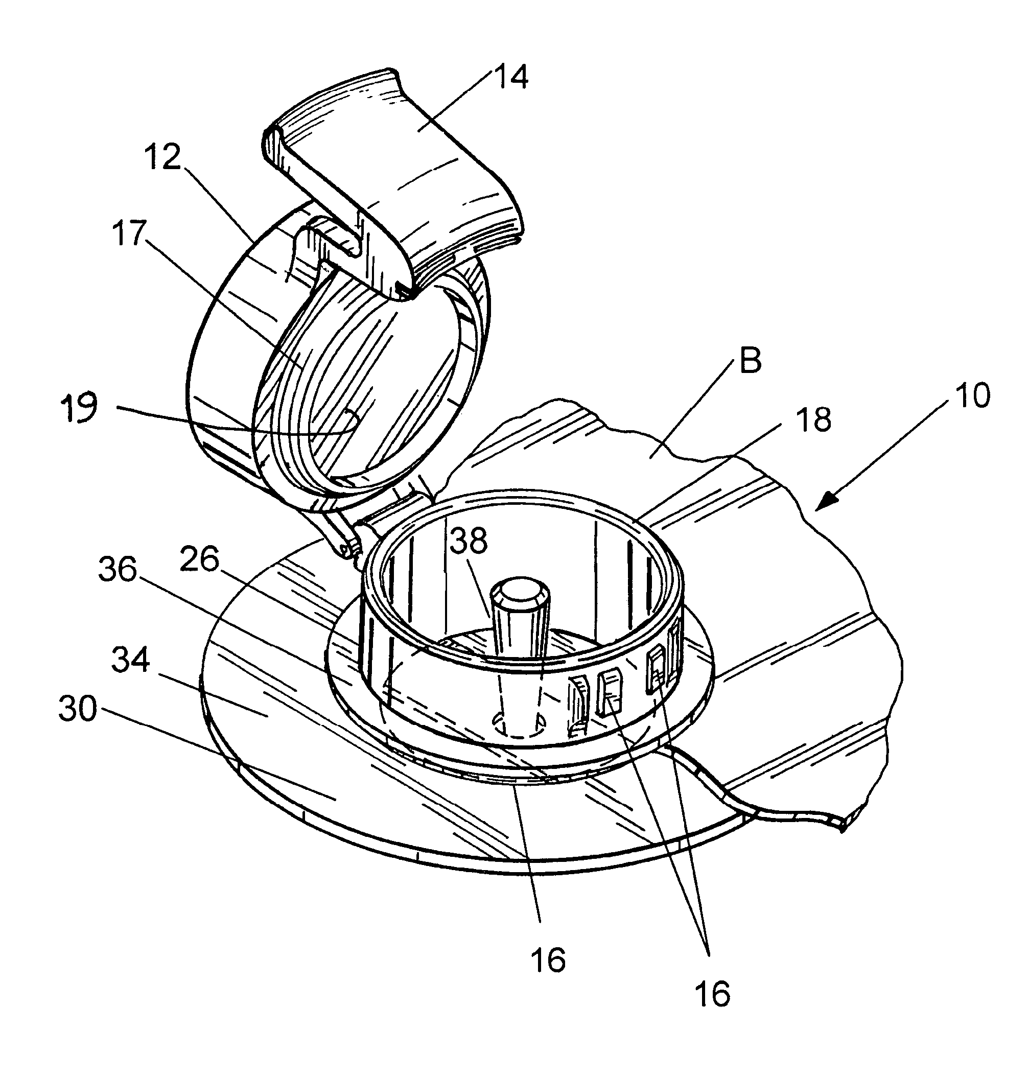
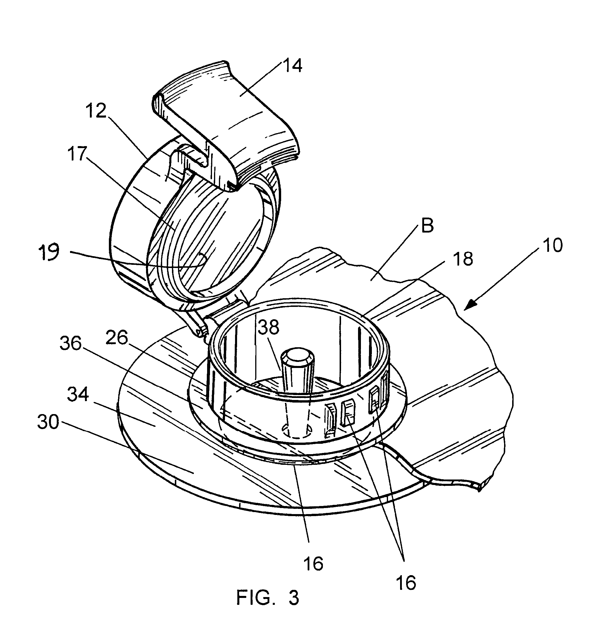
[0031]In use, the bags are located in the desired space in the cargo container and inflated to a preferred pressure. It is important that the valve assembly 10 attached to the dunnage bag be simple and reliable in use, otherwise the loading process will be delayed. Likewise, it is important that the valve assembly 10 retain a good seal thr...


PUM


Abstract

A valve assembly for a dunnage bag wherein in the valve body a valve diaphragm is mounted on a shaft and is supported by a mounting bar such that the valve diaphragm may be reciprocally moved from the closed position to the open position by a simple axial push on the valve shaft. The valve shaft is retained in the mounting bar in an orifice and the shaft diameter is enlarged at its end distant from the valve diaphragm so as to generate a frictional force fit or lock in the open position to facilitate the removal of air from the bag. The valve may be released form the friction lock by the air pressure of a recharged bag and/or by the manual movement of the valve diaphragm and shaft axially toward the open end of the valve assembly.

Description

CROSS-REFERENCE TO RELATED APPLICATIONS[0001]NoneSTATEMENT REGARDING FEDERALLY SPONSORED RESEARCH OR DEVELOPMENT[0002]Not applicableREFERENCE TO A “MICROFICHE APPENDIX”[0003]Not applicableBACKGROUND OF THE INVENTION[0004]1. Field of the Invention[0005]The present invention relates to inflatable dunnage air bags as are utilized in securing cargo and / or freight in a cargo hold, such as a truck, rail car, aircraft or ship and more particularly, to an inflation valve therefor.[0006]2. General Background of the Invention[0007]Inflatable air bags are utilized in the cargo transportation industry to secure a load against undue movement during the transportation phase. While cargo is generally loaded as snugly into a vehicle as possible, such as a cargo hold of a truck or rail car, it is frequently of sufficiently irregular shape or varied size, it is not otherwise possible to ensure a tight fit during the loading process[0008]The transportation industry has adopted relatively large inflata...

Claims


Application Information

Patent Timeline
IPC IPC(8): F16K15/20
CPCF16K15/205B60P7/065Y10T137/3677Y10T137/7877Y10T137/3755Y10T137/3584Y10T137/7876
Inventor ROBBINS, JAMES A.
Owner ROBBINS JAMES A
Why Eureka
Try Eureka