Unlock instant, AI-driven research and patent intelligence for your innovation.

Signal processing device, image capturing device, network camera system and video system

a technology of image capturing and signal processing, which is applied in the field of signal processing devices, image capturing devices, network camera systems and video systems, can solve the problems of inability to achieve precise motion estimation and inability to perform motion estimation, and achieve the effect of reducing the search range for motion estimation and high coding efficiency

Inactive Publication Date: 2007-07-19
PANASONIC CORP
View PDF13 Cites 30 Cited by
  • Summary
  • Abstract
  • Description
  • Claims
  • Application Information

AI Technical Summary

Benefits of technology

[0022]An object of the present invention is to provide parallel processing of motion estimation of full pixel precision and motion estimation of half pixel precision, and high-precision motion estimation irrespective of a significant motion.
[0023]To achieve the object, the present invention provides a configuration of a reference image memory and a connection relationship between a reference image memory and a motion estimating circuit which allow both motion estimation of full pixel precision and motion estimation of half pixel precision to be performed in parallel, and allows a search range for motion estimation to be variably set.

Problems solved by technology

As a result, although the precision of motion estimation is improved, it disadvantageously takes a longer time to perform motion estimation.
Therefore, even when the motion of an image is significant, a search range for motion estimation is fixedly narrow, so that precise motion estimation cannot be achieved.

Method used


Image

  • Signal processing device, image capturing device, network camera system and video system
  • Signal processing device, image capturing device, network camera system and video system
  • Signal processing device, image capturing device, network camera system and video system

Examples


first example

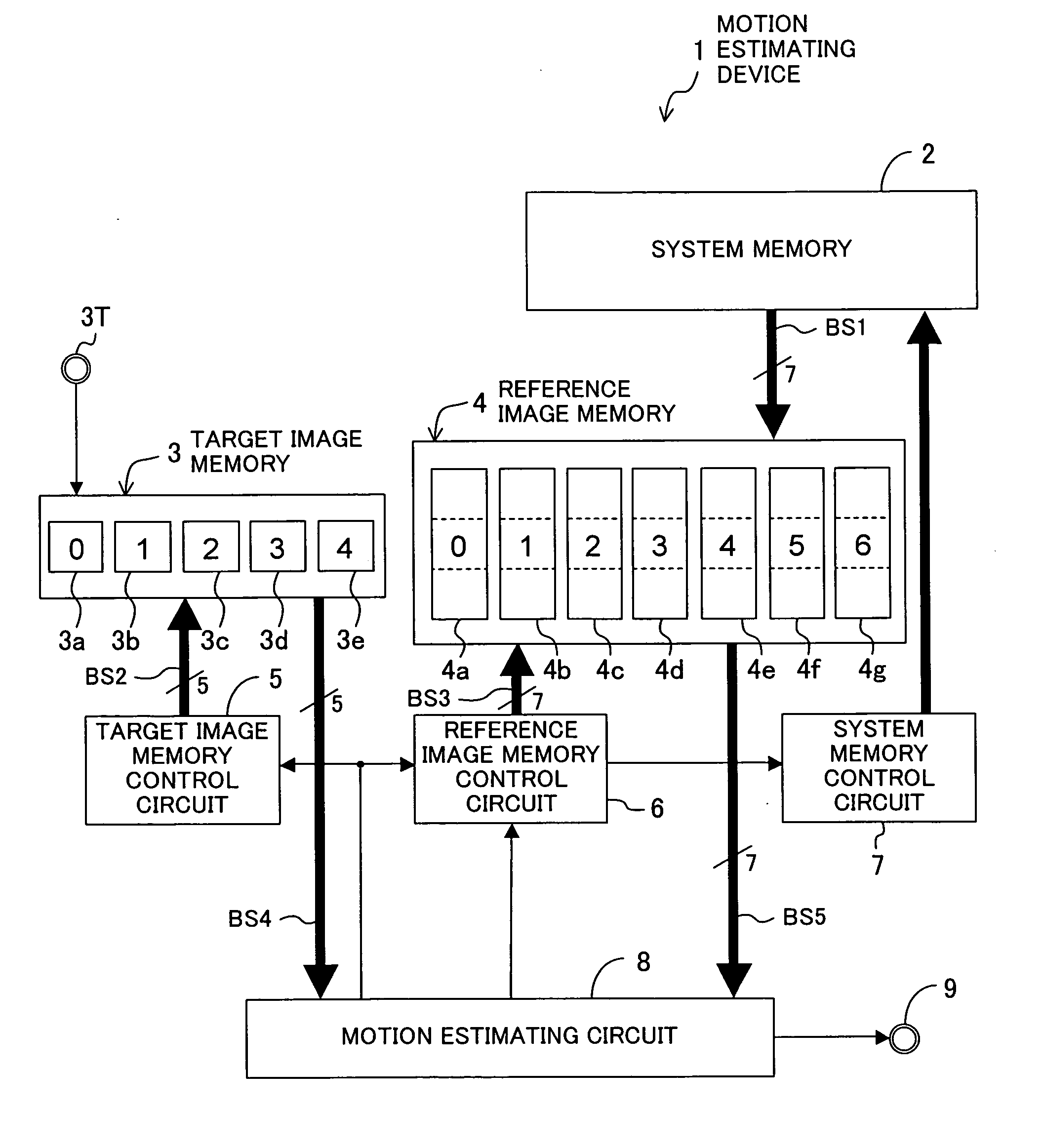
[0100]FIG. 1 illustrates a schematic whole configuration of a signal processing device according to an example of the present invention. The signal processing device of FIG. 1 is a device for estimating a motion in an image.

[0101]In the motion estimating device 1 of FIG. 1, 2 indicates a system memory, 3 indicates a target image memory, and 4 indicates a reference image memory. The system memory 2 has a capacity which can store at least one frame image. The target image memory (target image storing section) 3 successively receives pixel data of one macroblock which is a target of motion estimation (hereinafter referred to as a target macroblock) from a terminal 3T, and comprises five physically separate one-port target block memories 3a to 3e. Here, for example, a macroblock refers to a block of (x, y)=16 pixels×16 pixels as illustrated in FIG. 28. For example, image data including 8×8 macroblocks (i.e., 8 in the width direction and 8 in the length direction) constitute a frame imag...

second example

[0117]Next, a second example of the present invention will be described. This example relates to a motion estimating device in which a method of controlling motion estimation with respect to a target macroblock is not fixed and is changed as required.

[0118]The motion estimating device of this example is illustrated in FIGS. 4A and 4B. The whole configuration of the motion estimating device of FIGS. 4A and 4B is similar to that of the motion estimating device of FIG. 1. Note that, in FIGS. 4A and 4B, the target image memory 3 and the reference image memory 4 have larger capacities than those of FIG. 1.

[0119]In a motion estimating device 1 illustrated in FIG. 4A, required performance information Inf about required performance of an image, such as image quality (a bit rate, etc.), a size, a frame rate or the like of the image, is input to a motion estimating circuit (bank configuration specifying section) 8. When the input required performance information Inf indicates that required im...

third example

[0122]Next, a motion estimating device according to a third example of the present invention will be described. Although a method of controlling motion estimation of a target macroblock is changed in the second example, a search range for motion estimation is changed in this example.

[0123]FIGS. 5A and 5B illustrate a whole configuration of a motion estimating device 1 according to this example. As in the first example, the motion estimating circuit 8 of FIGS. 5A and 5B performs a motion estimation control method in which motion estimation of full pixel precision, motion estimation of half pixel precision, and spare transfer for image data of a reference macroblock for motion estimation with respect to the next target macroblock are performed in parallel. As in the second example, the motion estimating circuit 8 receives required performance information Inf about required performance of an image, such as image quality, a size, a frame rate or the like of the image. Based on the requi...


PUM


Abstract

A reference image memory comprises seven reference bank memories each having a capacity which can store three reference macroblocks in the vertical direction. Of the seven reference bank memories, any three reference bank memories are adaptively allocated to motion estimation of full pixel precision, any other three reference bank memories are adaptively allocated to motion estimation of half pixel precision, and remaining one reference bank memory is adaptively allocated to spare transfer for image data of a reference macroblock used in motion estimation with respect to the next target macroblock. The reference bank memories are connected to a motion estimating circuit via a total of seven respective buses separately. The motion estimating circuit performs the motion estimation of full pixel precision, the motion estimation of half pixel precision, and the spare transfer for image data of a reference macroblock used in motion estimation with respect to the next target macroblock, in parallel.

Description

CROSS REFERENCE TO RELATED APPLICATIONS[0001]This Non-provisional application claims priority under 35 U.S.C. §119(a) on Patent Application No. 2006-006112 filed in Japan on Jan. 13, 2006, the entire contents of which are hereby incorporated by reference.BACKGROUND OF THE INVENTION[0002]1. Field of the Invention[0003]The present invention relates a signal processing device for estimating a motion vector in motion-compensated predictive coding, which is a moving image compression method, and an image capturing device, a network camera system, and a video system which employ the signal processing device. More particularly, the present invention relates to an improvement in the speed of a motion estimation process and the efficiency of coding.[0004]2. Description of the Related Art[0005]At present, an advanced signal processing technique of compressing an image with a high compression ratio is used in digital cameras or digital camcorders.[0006]As a method of compressing moving images,...

Claims


Application Information

Patent Timeline
IPC IPC(8): H04N7/12H04N11/04G06T1/20H04N19/50G06T1/60G06T7/20H04N19/105H04N19/136H04N19/137H04N19/154H04N19/423H04N19/436H04N19/503H04N19/523H04N19/577H04N19/61H04N19/625H04N19/91
CPCH04N19/433
Inventor KITAMURA, SHINJITANAKA, YASUHARU
Owner PANASONIC CORP