Pulsed excitation and sampled detection fluxgate type magnetometer

Inactive Publication Date: 2007-07-26
COMMISSARIAT A LENERGIE ATOMIQUE ET AUX ENERGIES ALTERNATIVES
View PDF6 Cites 16 Cited by
  • Summary
  • Abstract
  • Description
  • Claims
  • Application Information

AI Technical Summary

Problems solved by technology

For a micro-fluxgate magnetometer, the wave shape, the amplitude, the frequency, the phase between the excitation signal and the synchronous detection are parameters independent of each other, which restricts the suitability of the device to a single operating frequency.
This phase problem is the re

Method used


Image

  • Pulsed excitation and sampled detection fluxgate type magnetometer
  • Pulsed excitation and sampled detection fluxgate type magnetometer
  • Pulsed excitation and sampled detection fluxgate type magnetometer

Examples


first embodiment

[0033] the sampling means may be provided, following said emission of said given pulse, to carry out an acquisition of the output signal of the sensor during a given time interval less than the duration of said given pulse, said time interval being between an instant situated at a predetermined time frame, preferably not zero, after the start of said pulse and an instant situated at another predetermined time frame, preferably not zero, before the end of said given pulse. This may make it possible to carry out an acquisition of the signal at an instant when electromagnetic, capacitive or / and inductive coupling phenomena are minimised or non-existent.

[0034]According to this first embodiment, the sampling means may be further provided to carry out an averaging or a smoothing out of the output signal of the magnetic sensor during said given time interval.

[0035]A signal known as “smoothed out” may be formed following said averaging or said smoothing out of the output signal. According t...

second embodiment

[0041] the sampling means may be provided to carry out a memorization of the output signal of the sensor at said given predetermined instant.

[0042]According to the second embodiment, the sampling means may comprise at least one sampler-blocker.

[0043]According to one variant, the sampling means may be further capable, following the emission of a pulse, of carrying out an analog to digital conversion of the output signal of the circuit as of or at said given predetermined instant. The sampling means may comprise means forming an analog to digital converter.

[0044]According to one embodiment of the measuring device, this device is capable of slaved operating and may comprise one or several feedback windings, and a feedback loop equipped with means for producing a feedback signal intended for said feedback windings.

[0045]Said means for producing a feedback signal may comprise means forming at least one integrator.

[0046]Said means for producing a feedback signal may comprise means for mem...

third embodiment

[0082]FIGS. 7A and 7B, illustrate respectively:[0083]a magnetic field measuring device according to the invention comprising a fluxgate magnetometer type sensor and improved sampling means at the output of the sensor,[0084]and excitations signals from the magnetic sensor and control of said sampling means, employed within such a device;

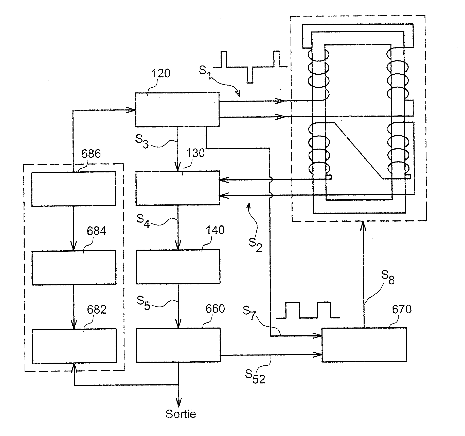
[0085]FIG. 8 illustrates an example of slaved operating magnetic field measuring device according to the invention,

[0086]FIGS. 9 and 10 illustrate respectively:[0087]another example of slaved operating magnetic field measuring device according to the invention and equipped with means for generating a feedback signal, said feedback signal being delivered by means controlled by a “pulsed” control signal,[0088]a chronogram of the operation of this example of device;

[0089]FIG. 11 illustrates another example of slaved operating magnetic field measuring device according to the invention and equipped with means to modulate the frequency of repetition of the ...


PUM


Abstract

The invention concerns a magnetic field measuring device equipped with a fluxgate magnetometer, the device comprising: a magnetic sensor or magnetic sensor (110,210) capable of delivering at least one output signal (S2), and equipped with at least one magnetic core, means of exciting said magnetic core, comprising generating means (120,220,420) capable of emitting an excitation signal (S1, S10) at the input of the circuit or magnetic sensor, in the form of a succession of pulses (125,126,225,226), means (130,230,330,430) of sampling the output signal (S1) of the magnetic circuit (110,210), further comprising means for: following the emission of at least one given pulse of said succession of pulses, triggering at least one acquisition of the output signal (S2) of the magnetic circuit by the sampling means during the duration of said given pulse. The invention further concerns a method employed by means of such a device.

Description

TECHNICAL FIELD[0001]The present invention relates to the field of magnetometers or magnetic sensors, and employs an electronic or microelectronic magnetic field detection or / and measuring device, comprising a fluxgate type magnetometer magnetic sensor, as well as improved means of pulsed excitation of the sensor and sampled detection at the output of the sensor. The invention further concerns an improved method of detection or / and measuring by means of such a device.[0002]The device and method according to the invention bring improvements, particularly in terms of signal to noise ratio, consumption and bandwidth.STATE OF THE PRIOR ART[0003]“Fluxgate” type magnetometers find use in measuring magnetic fields, which may be weak or even very weak, for example of around one microtesla with a resolution of around one nanotesla or even around several picoteslas, depending on the dimensions of the magnetometer. Magnetometers can be applied to the field of microelectronics and be incorporat...

Claims


Application Information

Patent Timeline
IPC IPC(8): G01R33/04
CPCG01R33/04
Inventor BERANGER, MARC
Owner COMMISSARIAT A LENERGIE ATOMIQUE ET AUX ENERGIES ALTERNATIVES
Why Eureka
Try Eureka