LED backlight unit

Active Publication Date: 2007-08-23
SAMSUNG ELECTRONICS CO LTD
View PDF18 Cites 39 Cited by
  • Summary
  • Abstract
  • Description
  • Claims
  • Application Information

AI Technical Summary

Benefits of technology

[0024]The present invention has been made to solve the foregoing problems of the prior art and therefore an aspect of the present invention is to pr

Problems solved by technology

In general, the LCD fails togenerate light voluntarily, which thus necessitates a backlight unit including a light source for generating light and a light guide plate on a rear si

Method used


Image

  • LED backlight unit
  • LED backlight unit
  • LED backlight unit

Examples


Example

[0041]Exemplary embodiments of the present invention will now be described in detail with reference to the accompanying drawings.

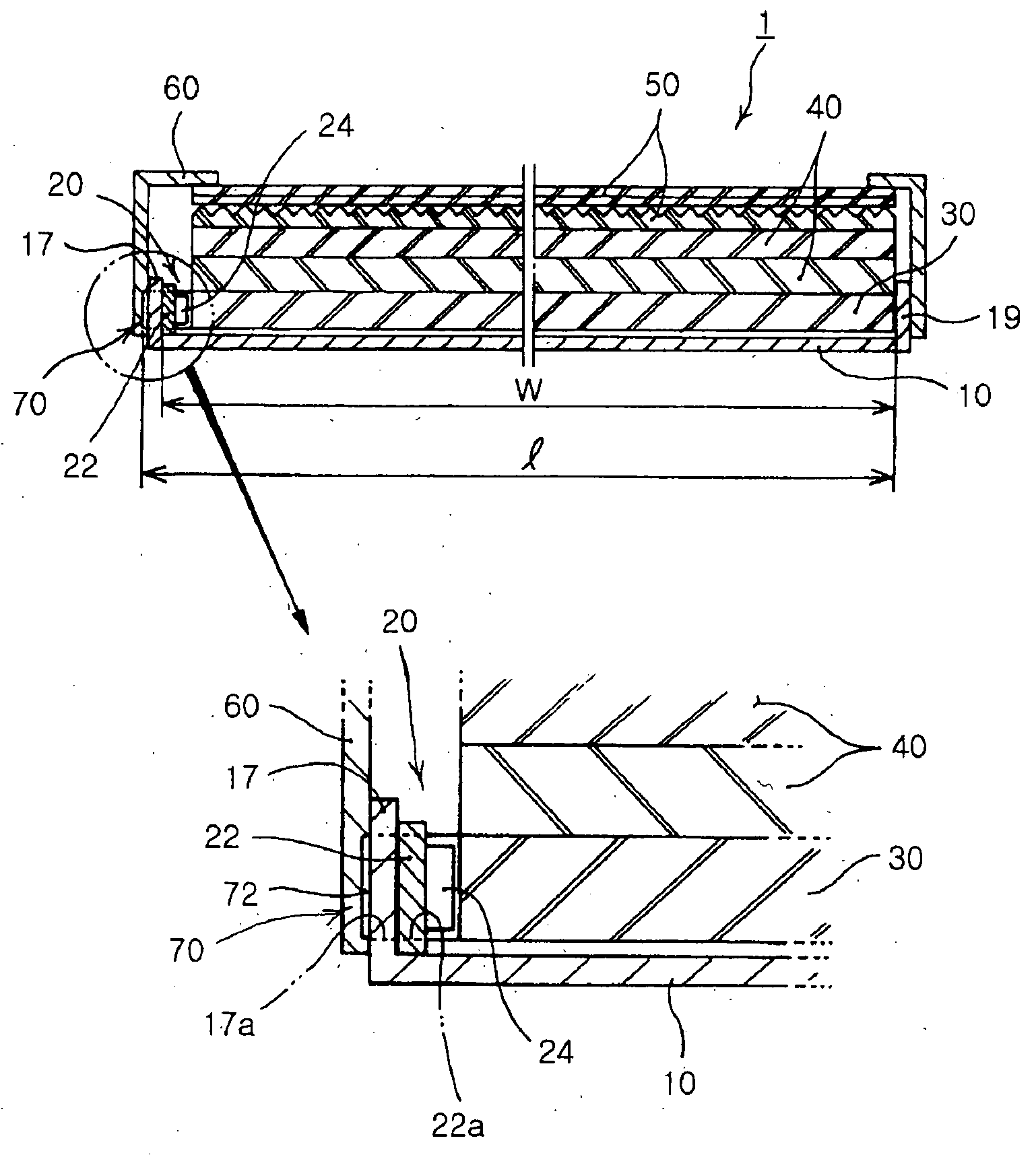
[0042]As shown in FIG. 4, a light emitting diode (LED) backlight unit 1 according to the invention includes a light source having a substrate 22 and a plurality of LEDs 24 disposed on a substrate 22, and a light guide plate 30 placed adjacent to the light source 20.

[0043]Also, the LED backlight unit 1 includes a lower chassis 10, a plurality of diffuser plates 40, a plurality of prism plates 50 and a middle chassis 60. The lower chassis 10 fixes the light source 20 and the light guide plate 30 therein. The diffuser plates 40 are disposed over the light guide plate 30 and the prism plates 50 are disposed over the diffuser plates 40. The middle chassis 60 is located to fix the lower chassis 10, the diffuser plates 40 and the prism plates 50.

[0044]Further, according to the invention, fixing means 70 are disposed to engagingly fit a side of the light guide pla...


PUM


Abstract

An LED backlight unit which can be assembled without a thermosetting adhesive, improved in heat radiation effects to maintain high brightness, and also significantly improved in productivity. A light source has a substrate and a plurality of light emitting diodes disposed on the substrate. A light guide plate is placed adjacent to the light source. A chassis fixes the light source and the light guide plate therein. Fixing means engagingly fit a side of the light guide plate into the light source plate and chassis. Here, the substrate of the light source is fixed in surface contact with the chassis. The light guide plate assemblable without a thermosetting adhesive facilitates assembling and ensures effective radiation of heat generated from the LED, thereby maintaining high brightness and achieving superb light emitting capability.

Description

CLAIM OF PRIORITY[0001]This application claims the benefit of Korean Patent Application No. 2006-16702 filed on Feb. 21, 2006 in the Korean Intellectual Property Office, the disclosure of which is incorporated herein by reference.BACKGROUND OF THE INVENTION[0002]1. Field of the Invention[0003]The invention relates to a backlight unit using a light emitting diode, and more particularity, to a light emitting diode (LED) backlight unit in which a light guide plate is assembled without a thermosetting adhesive affecting brightness of the LED, and which assures higher radiation efficiency of heat generated from the LED, thereby maintaining high brightness, and significantly enhancing productivity.[0004]2. Description of the Related Art[0005]Development in the electronic device industry also has led to development in various small display devices with less energy consumption rate, and in image devices, computers and telecommunication terminals using such display devices. A liquid crystal ...

Claims


Application Information

Patent Timeline
IPC IPC(8): F21V7/04
CPCG02B6/0021G02B6/0091G02B6/0085G02B6/0068G02B6/0013G02B6/0073G02F1/1335
Inventor SHIN, CHANG HO
Owner SAMSUNG ELECTRONICS CO LTD
Why Eureka
Try Eureka