Eureka AIR delivers breakthrough ideas for toughest innovation challenges, trusted by R&D personnel around the world.

Low-pressure mercury vapor discharge lamp with improved heat dissipation, and manufacturing method therefore

Inactive Publication Date: 2005-12-06
PANASONIC CORP
View PDF10 Cites 2 Cited by
  • Summary
  • Abstract
  • Description
  • Claims
  • Application Information

AI Technical Summary

Benefits of technology

[0010]A first object of the present invention is to provide a low-pressure mercury vapor fluorescent lamp capable of preventing temperature rise at a surrounding portion of the lighting circuit. A second object of the present invention is to provide a method for manufacturing a low-pressure mercury vapor fluorescent lamp with enhanced productivity.
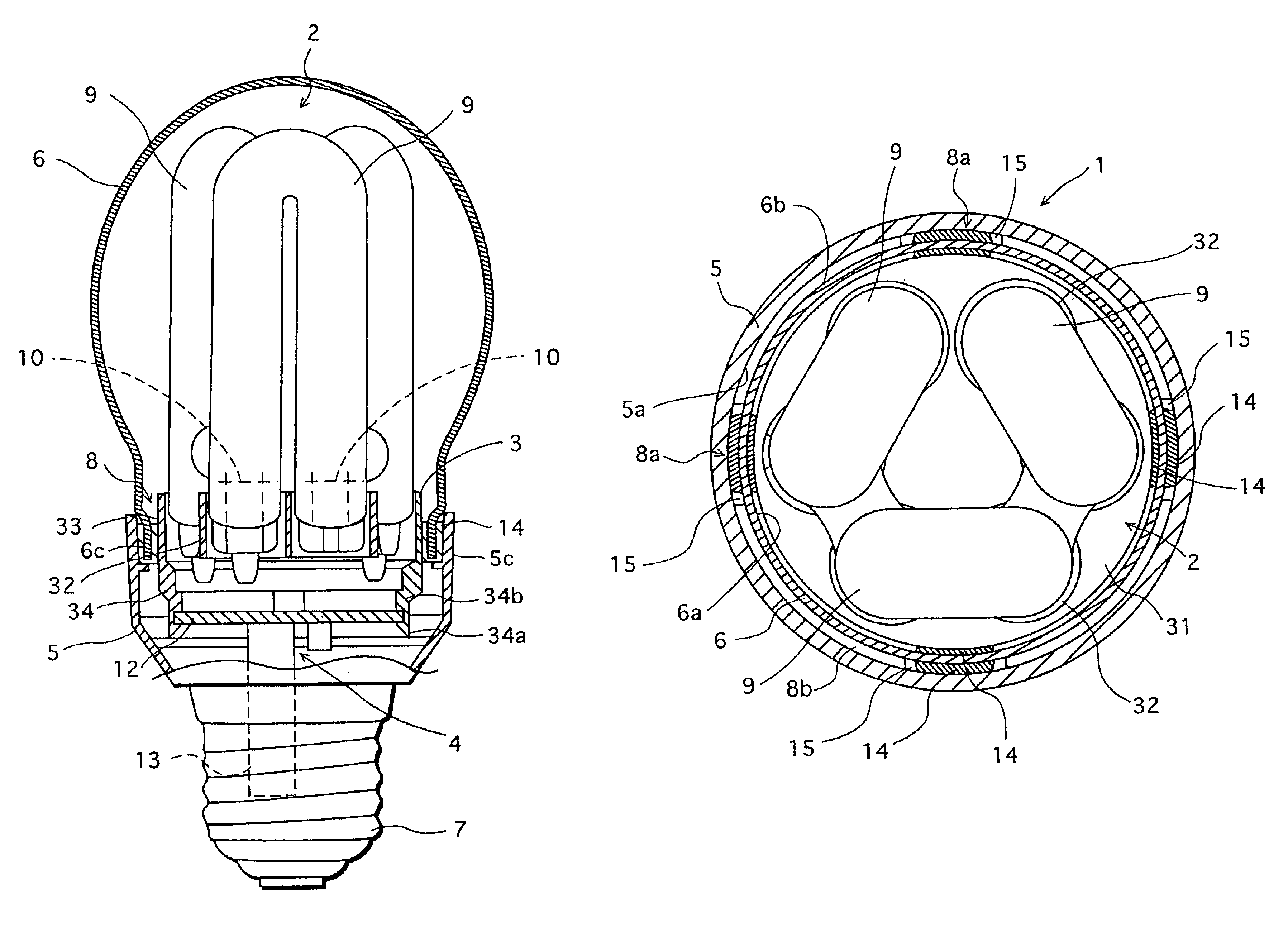
[0011]The above-stated first object of the present invention is achieved by a low-pressure mercury vapor discharge lamp that has: an envelope formed of a case and a globe each having an open end, the case and the globe being loosely fitted together by inserting one open end into the other; an arc tube covered by the globe; and a lighting circuit housed in the case. Here, the case and the globe are partially bonded to each other along a circumferential surface of where the case and the globe overlap as the result of insertion. With this arrangement, in the overlapping surface of the case and the globe, there remains an area that the case and the globe are not bonded in the circumferential direction. Air present in the non-bonded area functions as heat insulator, so that heat generated by the arc tube is prevented from being conducted from the globe to the case. In addition, the heat generated from the arc tube is released outside through the non-bonded area. As a consequence, temperature rise in the envelope is prevented. That is to say, temperature rise around the lighting circuit housed in the envelope is suppressed, so that the circuit components are kept from being damaged and remain reliable.
[0012]Further, the second object of the present invention sated above is achieved by a method for manufacturing a low-pressure mercury vapor lamp provided with a globe attached to a case so as to house an arc tube therein. The method includes: a sticking agent supplying step of supplying a sticking agent to the case in an area of a circumferential surface of an open end portion to be attached to the globe; and a fitting step of loosely fitting together an open end portion of the globe and the open end portion of the case so that the globe overlaps the area of the case where the sticking agent is supplied. With this method, in contrast to a conventional method in which the sticking agent is supplied along the entire periphery of the open end portion of the case, the area to which the sticking agent is supplied is smaller, so that the time taken to supply the sticking agent is shortened. In addition, the usage amount of sticking agent is made smaller in comparison with the conventional method, which leads to that the cost of the sticking agent is reduced.

Problems solved by technology

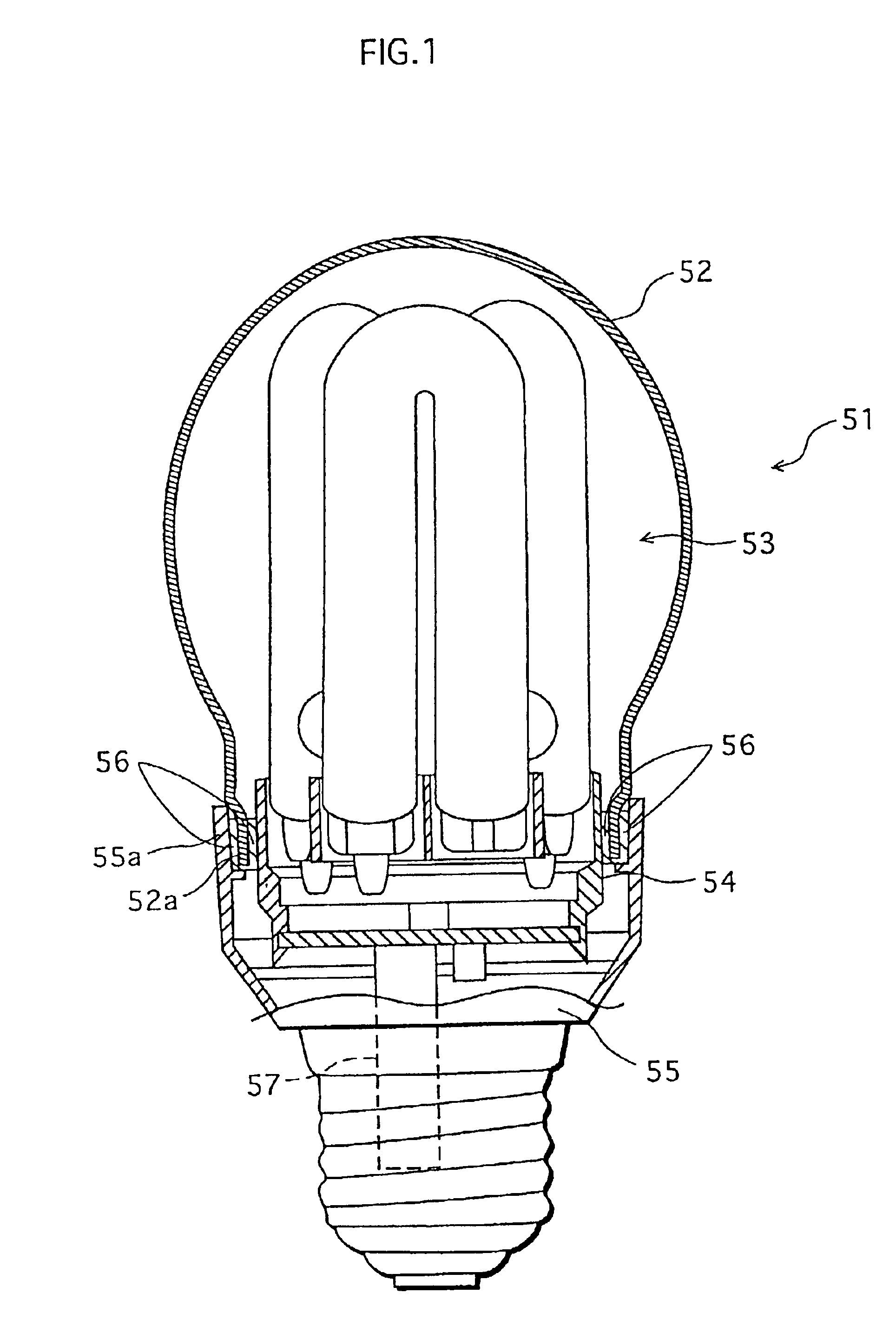
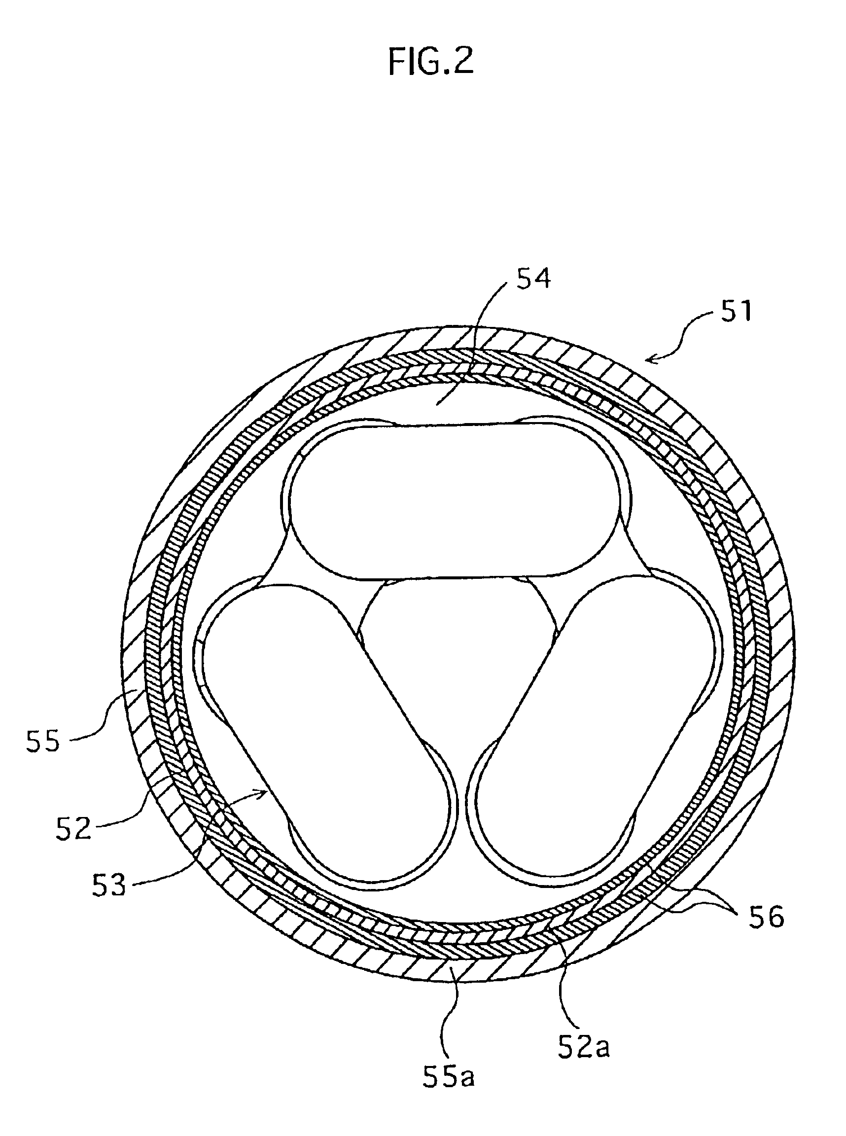
Being exposed to such a high temperature, components constituting the lighting circuit 57 become less reliable, if not damaged.
Another problem lies in the manufacturing method.
Such a supplying process is time consuming, and thus undesirably reduces productivity in manufacturing such fluorescent lamps.

Method used


Image

  • Low-pressure mercury vapor discharge lamp with improved heat dissipation, and manufacturing method therefore
  • Low-pressure mercury vapor discharge lamp with improved heat dissipation, and manufacturing method therefore
  • Low-pressure mercury vapor discharge lamp with improved heat dissipation, and manufacturing method therefore

Examples


Embodiment Construction

[0027]Now, description is given to one embodiment in which the present invention is applied to a bulb-type fluorescent lamp with reference to the accompanying drawings.[0028]1. Construction of Bulb-Type Fluorescent Lamp FIG. 3 is a partly-broken, oblique view showing a bulb-type fluorescent lamp. As shown in the figure, the bulb-type fluorescent lamp 1 is composed of: an arc tube 2 forming a serpentine discharge path; a holder 3 holding the arc tube 2; a lighting circuit 4 for lighting the arc tube 2, arranged on the opposite side of the holder 3 to the arc tube 2 (see FIG. 4); a case 5 housing the lighting circuit 4 therein; and a transparent globe 6 fixedly attached to the case 5 with an adhesive 14 (see FIG. 4) in a manner to cover the arc tube 2.

[0029]The case 5 and the globe 6 each has an open end portion, and are loosely fitted together at their respective open end portions with a circumferential clearance therebetween, thereby forming an envelope. The case 5 is also provided ...


PUM


Abstract

A bulb-type fluorescent lamp has a case having an open end portion for housing a lighting circuit therein, an arc tube extending outside through the open end portion of the case, and a globe having an open end portion for housing the arc tube therein. An adhesive is supplied to the inner surface of the open end portion of the case at four circumferentially spaced areas, and the open end portion of the globe is inserted into the open end portion of the case. As a result, the globe is fixed to the case with the adhesive.

Description

[0001]This application is based on an application No. 2001-307587 filed in Japan, the content of which is hereby incorporated by reference.BACKGROUND OF THE INVENTION[0002](1) Field of the Invention[0003]The present invention relates to a low-pressure mercury vapor discharge lamp provided with a globe housing an arc tube therein, and to a manufacturing method therefore. Especially, the present invention relates to a bulb-type fluorescent lamp.[0004](2) Description of the Related Art[0005]A bulb-type fluorescent lamp, which is one type of a low-pressure mercury vapor discharge lamp, has higher luminance efficacy and a longer life in comparison with a filament lamp. Due to these advantages, a bulb type fluorescent lamp is recognized as an energy-saving lighting apparatus, and thus rapidly becoming prevalent.[0006]FIG. 1 shows a partly-broken, vertical sectional view showing the construction of a conventional bulb-type fluorescent lamp. As shown in the figure, the bulb-type fluorescent...

Claims


Application Information

Patent Timeline
IPC IPC(8): F21S2/00F21Y103/37H01J5/48H01J5/50H01J9/24H01J61/30
CPCH01J5/48H01J5/50H01J9/247F21V31/03F21V17/101
Inventor ITAYA, KENJIMATSUMURA, TAKESHIKAKUNO, YOSHINORI
Owner PANASONIC CORP
Why Eureka
Eureka Blog
Learn More