Downtime monitoring apparatus and method

Inactive Publication Date: 2010-08-05
TM IND
View PDF8 Cites 2 Cited by
  • Summary
  • Abstract
  • Description
  • Claims
  • Application Information

AI Technical Summary

Benefits of technology

[0025]In some forms of the invention, a record is compiled of the timing and duration of the operation of the signal units in various modes. This record may then be used, in some

Problems solved by technology

Although the automation of machinery and processes has reached a level of sophistication which could not have even been dreamed of only a few years ago, most automated processes still require some degree of supervision and oversight by human operators.
Even in settings where fully automated processes are possible, at least theoretically, the financial burden to put such fully automated processes in place is often prohibitive.
Such traditional andon systems are less than desirable for a number of reasons.
For example, it can be difficult to provide a central location for t

Method used


Image

  • Downtime monitoring apparatus and method
  • Downtime monitoring apparatus and method
  • Downtime monitoring apparatus and method

Examples


Example

[0037]While the invention is described in connection with certain preferred embodiments, there is no intent to limit the invention to those embodiments. On the contrary, the intent is to cover all alternatives, modifications and equivalents as included within the spirit and scope of the invention.

DETAILED DESCRIPTION OF THE INVENTION

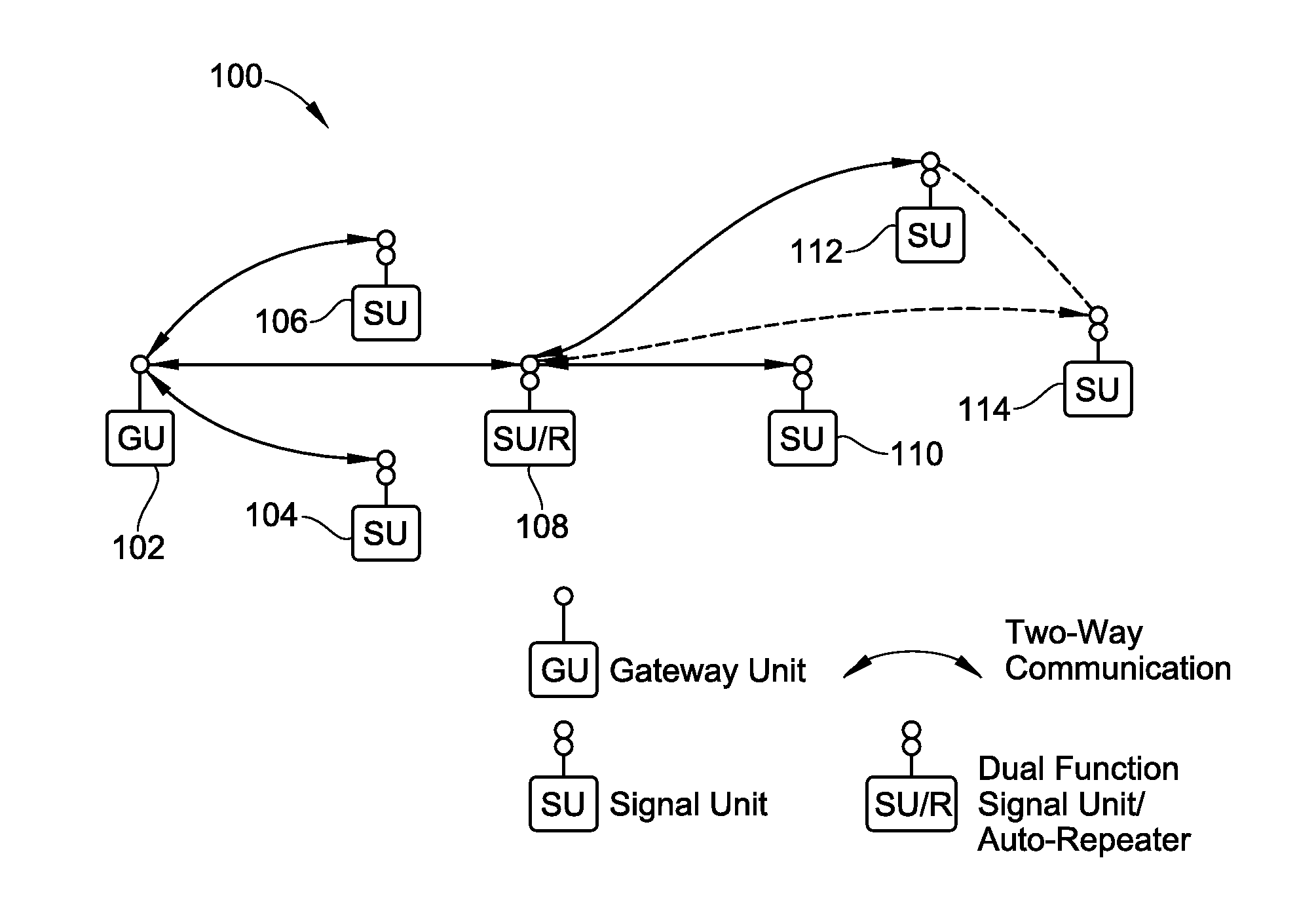
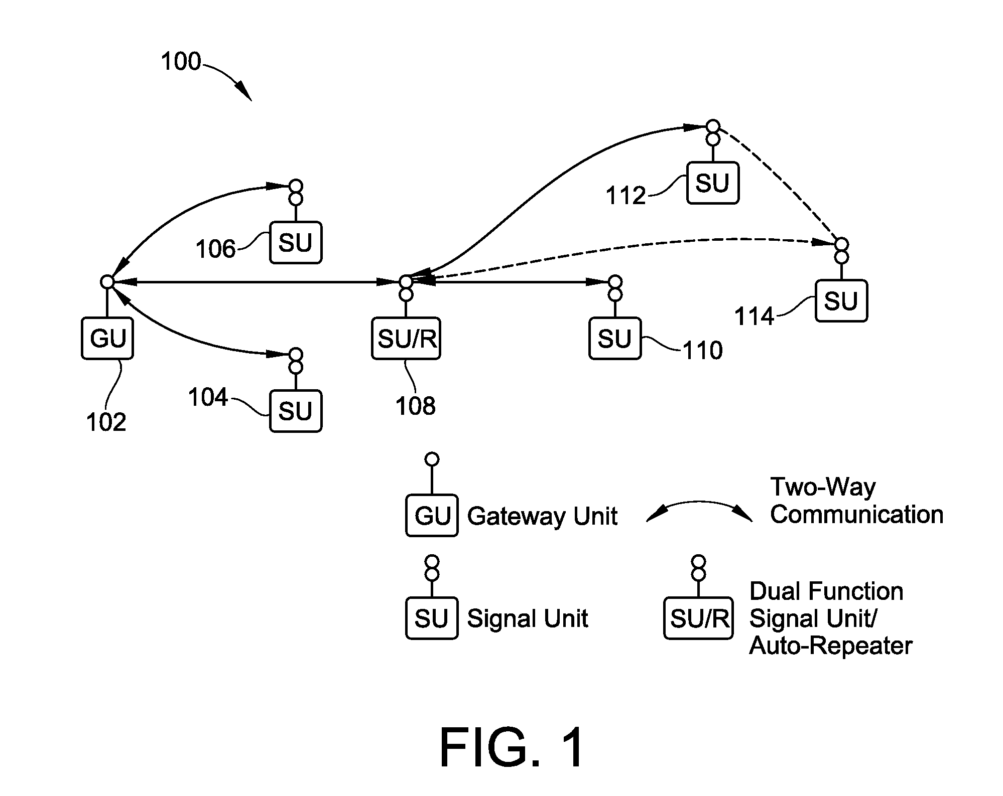
[0038]FIG. 1 shows a first exemplary embodiment of a downtime monitoring system 100, according to an embodiment of the invention. The first exemplary embodiment of the monitoring system 100 includes one gateway unit 102 and six signal units 104, 106, 108, 110, 112, 114. The signal units 104, 106, 108, 110, 112, 114 are shown as they might be arrayed on a factory floor, for example, with each of the signal units 104, 106, 108, 110, 112, 114 being disposed adjacent a given process station (not shown) for use in performing a process.

[0039]In the exemplary embodiment of the monitoring system 100, all of the signal units 104, 106, 108, 110, 112, 114 are ident...


PUM


Abstract

An apparatus and method are provided for monitoring and facilitating a process, through the use of wirelessly-linked, portable signal units. The signal units have one or more signal lights, and can be placed adjacent to process stations. When a signal light is actuated by operator input at one or more of the process stations, the lights at all of the other process stations also are illuminated in a recognizable pattern to enhance visibility and identification at a glance as to which process station needs attention. Signal units also can function as repeaters to facilitate communication and operation. Designation of certain signal units as repeaters and optimization of communication between signal units is automatically carried out in accordance with one or more optimization approaches. In an embodiment, a time-based record of operation of the signal lights is provided for process monitoring and improvement.

Description

CROSS-REFERENCE TO RELATED PATENT APPLICATIONS[0001]This patent application claims the benefit of U.S. Provisional Patent Application No. 61 / 148,779, filed on Jan. 30, 2009, the entire teachings and disclosure of which are incorporated herein by reference thereto.FIELD OF THE INVENTION[0002]This invention relates generally to processes in manufacturing, assembly, fabrication used in commercial and industrial settings, and more particularly to a portable and adaptable system and method for use in such settings for monitoring and correcting problem conditions and for enhancing quality and productivity.BACKGROUND OF THE INVENTION[0003]Since the industrial revolution, almost every aspect of the manufacturing, assembly, storage, shipping, distribution and sale of products has become increasingly automated. Many processes are carried out in an assembly-line fashion with operations being performed sequentially at a number of successively arranged stations. In other settings, a number of hi...

Claims


Application Information

Patent Timeline
IPC IPC(8): G08B5/00H04B3/36
CPCH04B3/36
Inventor TABOR, KENTNOWAK, RYAN
Owner TM IND
Why Eureka
Try Eureka