Swivel snap hook of synthetic resin

Inactive Publication Date: 2001-11-08
YKK CORP
View PDF0 Cites 2 Cited by
  • Summary
  • Abstract
  • Description
  • Claims
  • Application Information

AI Technical Summary

Benefits of technology

0013] The base end of the stopper piece is preferred not to be elastically deformed directly, and has such a structure that the base end is not broken even if a strong external force is applied to some extent. On the other hand, although the hook body and a belt-connecting ring are different in design from the conventional ones, the structure, operation, and effect thereof are not different.
0014] Although according to the prior art, the swivel sn

Problems solved by technology

Therefore, a number of production steps are required, thereby raising its production cost.
Further, such a swivel snap hook is difficult to color in a durable fashion.
Thus, the swivel snap hook tends to have a poor appearance and is unsuitable for a traveler's bag, a shoulder bag and the like.
Therefore, troublesomeness for that process still exist, with a result that the production cost is raised to some extent.
However, even if it is intended to form the gap between the front-end outside engaging face of the stopper piece and the front-end inside engaging face of the hook body to its minimum size, the gap has such a size that does not generate a fusion of the engaging faces at the time of molding, so the depth of the hook body is required to be large to that extent, which is not desirable in terms of appearance.
If it is intended to form a molding cavity for the protrusion such that it communicates with a molding cavity for the front-end inside engaging face of the hook body and is slightly apart from the molding cavity for the front end of the stopper piece, high precision

Method used


Image

  • Swivel snap hook of synthetic resin
  • Swivel snap hook of synthetic resin
  • Swivel snap hook of synthetic resin

Examples


first embodiment

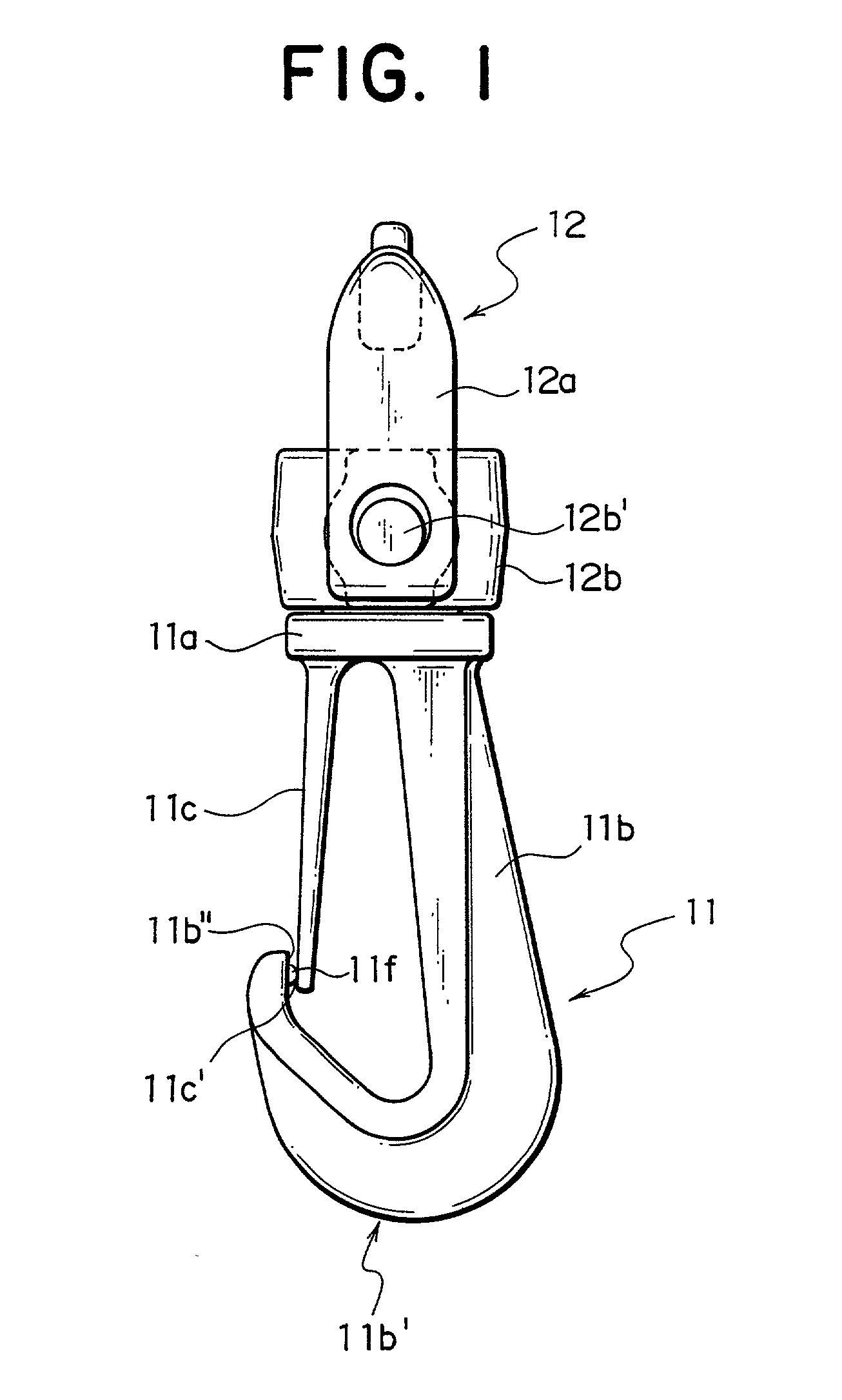
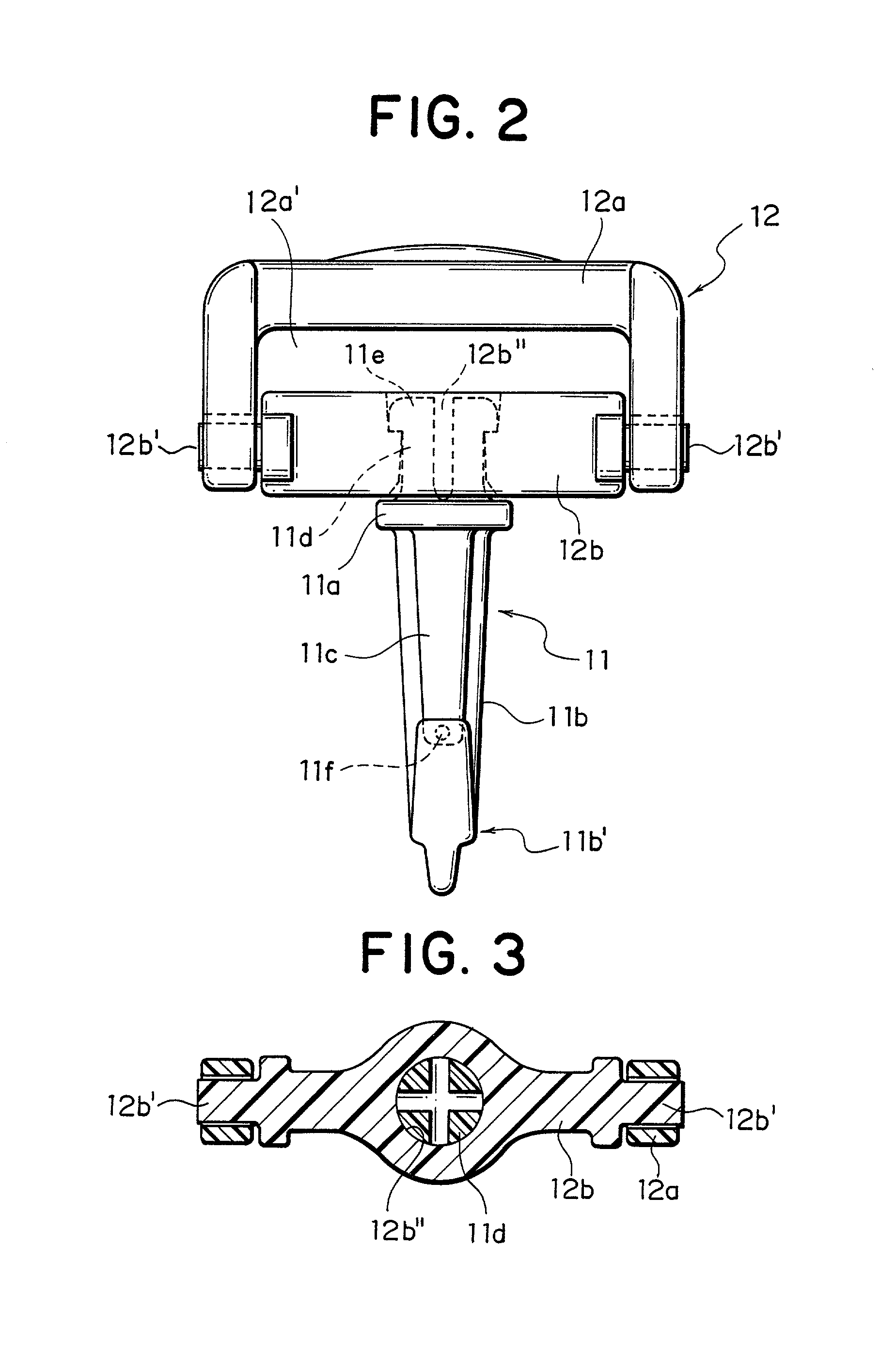
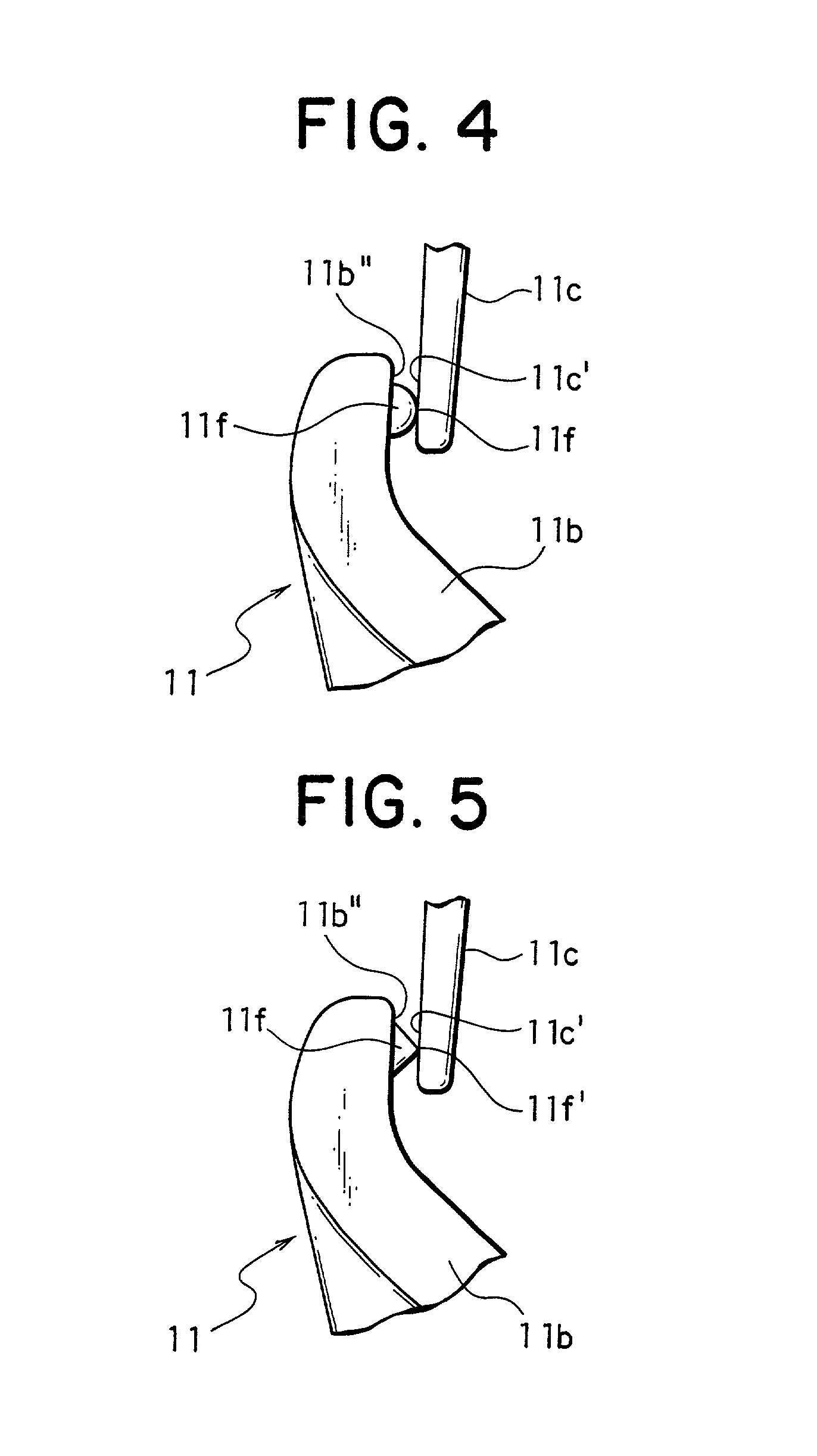
[0035] FIGS. 1 to 4 show the present invention. FIG. 1 is a front view of a swivel snap hook, FIG. 2 is a side view thereof, FIG. 3 is a top view thereof, and FIG. 4 is an enlarged front view thereof. Referring to these Figures, a swivel-snap-hook main body 11 is comprised of a disc-shaped base portion 11a, a hook body 11b protruded from a surface of the base portion 11a having a substantially T-shaped section, and a stopper piece 11c extended from the surface of the base portion 11a so as to oppose an inner face of a base of the hook body 11b, up to a front-end inside engaging face 11b' of a curved portion 11b' of the hook body 11b. Further, on the other surface of the base portion 11a, the swivel-snap-hook main body 11 has a enlarged small-disc shaped engaging head portion 11e, via a small-diameter neck portion 11d. The neck portion 11d and the engaging head portion 11e are divided to four sections in a plan view as shown in FIG. 3 so that they can elastically deform in a diameter...

second embodiment

[0043] FIGS. 5 and 6 show the present invention. According to the aforementioned first embodiment, the protrusion 11f is molded in a form of a semi-sphere and the protrusion 11f is separated from the front-end outside engaging face 11c' of the stopper piece 11c. According to this second embodiment, on the other hand, a protrusion 11f is molded in a form of a triangle. Further, an edge line at a vertex of the triangle, that is a minute portion 11f', is integrally connected to the front-end outside engaging face 11c of the stopper piece 11c when the molding is carried out.

[0044] As a result, it never happens that the protrusion 11f and the stopper piece 11c are separated from each other due to a contraction at the time of molding so that the distance therebetween is increased. Further, the shape of a product after the molding and hardening, particularly the hook body 11b and the stopper piece 11c, is prevented from being displaced with respect to each other, so that a swivel-snap-hook...

third embodiment

[0046] FIG. 7 shows the present invention. This third embodiment is different from the first and second embodiments in that a rib-like protrusion 11h is provided below a protrusion 11f as mentioned above on an inner face of a curved portion 11b' of a hook body 11b. According to this third embodiment, the configuration of the aforementioned rib-like protrusion 11h is fin-shaped and its inside end face is located on an extension of an inside face of the front end of the stopper piece 11c. Further, the height of the rib-like protrusion 11h is set to be substantially equal to a gap between the stopper piece 11c and a bottom of the hook body 11b. Meanwhile, the configuration of the rib-like protrusion 11h is not restricted to the example shown here.

[0047] When the protrusion 11f is protruded from the front-end inside engaging face 11b" of the hook body 11b even though it is minute, an annular member (not shown) hooked by the hook body 11b is somewhat difficult to be removed off from the ...


PUM


Abstract

In a swivel snap hook having a hook body and a stopper piece, a protrusion, which is molded integrally with a front-end inside engaging face or a front-end outside engaging face of the hook body or the stopper piece, is provided so as to have a minute protruding height and be protruded toward a mating engaging face. Further, a minute portion at a tip end of the protrusion is molded integrally with the mating engaging face. Consequently, the swivel snap hook can be molded such that the front-end outside engaging face of the stopper piece is closed to the front-end inside engaging face of the hook body. Therefore, in the swivel snap hook, a length and a depth of the hook body thereof can be set as the conventional ones, while it can be molded in a state that the front-end outside engaging face of the stopper piece is kept in contact with the front-end inside engaging face of the hook body.

Description

[0001] 1. Field of the Invention[0002] The present invention relates to a swivel snap hook made of synthetic resin to be used for various kinds of bags, knapsacks and the like.[0003] 2. Description of the Related Art[0004] A metallic swivel snap hook of this kind, which has been often used, requires a number of components. Therefore, a number of production steps are required, thereby raising its production cost. Further, such a swivel snap hook is difficult to color in a durable fashion. Thus, the swivel snap hook tends to have a poor appearance and is unsuitable for a traveler's bag, a shoulder bag and the like. For the reason, the use of this kind of the swivel snap hook has been restricted to luxury goods. Therefore, instead of this kind of the metallic swivel snap hook, a swivel snap hook made of synthetic resin has been used in an increased number of fields. This swivel snap hook of synthetic resin ensures an excellent productivity, a low cost and a small weight.[0005] An examp...

Claims


Application Information

Patent Timeline
IPC IPC(8): F16B45/02A44B13/00
CPCF16B45/02Y10T24/45419Y10T24/45408A45C13/00A44B13/00F16B45/036F16B45/008
Inventor MATOBA, HIROSHIUEHARA, RYOICHIRO
Owner YKK CORP
Why Eureka
Try Eureka