

Coupling structure of electromagnetic valve for controlling water supply
- Summary
- Abstract
- Description
- Claims
- Application Information
AI Technical Summary
Benefits of technology
Problems solved by technology
Method used
Image

Examples
Embodiment Construction
[0020]Hereinafter, an exemplary embodiment of the present invention will be described in detail with reference to the accompanying drawings.
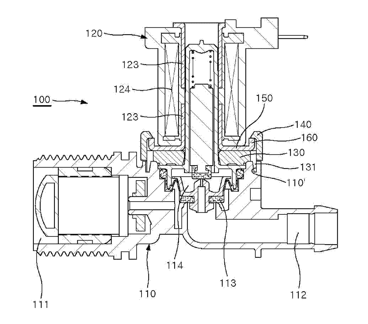
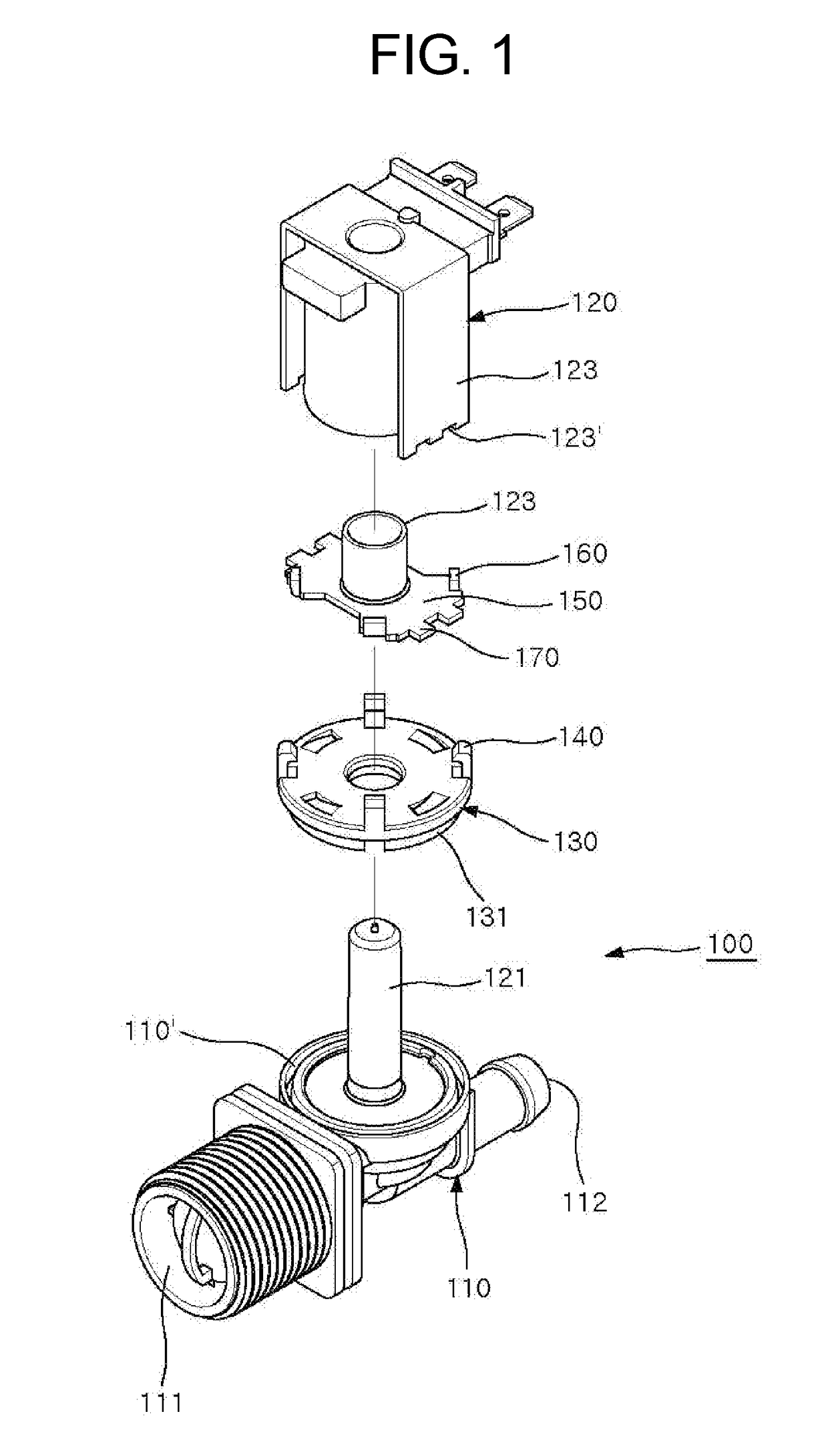
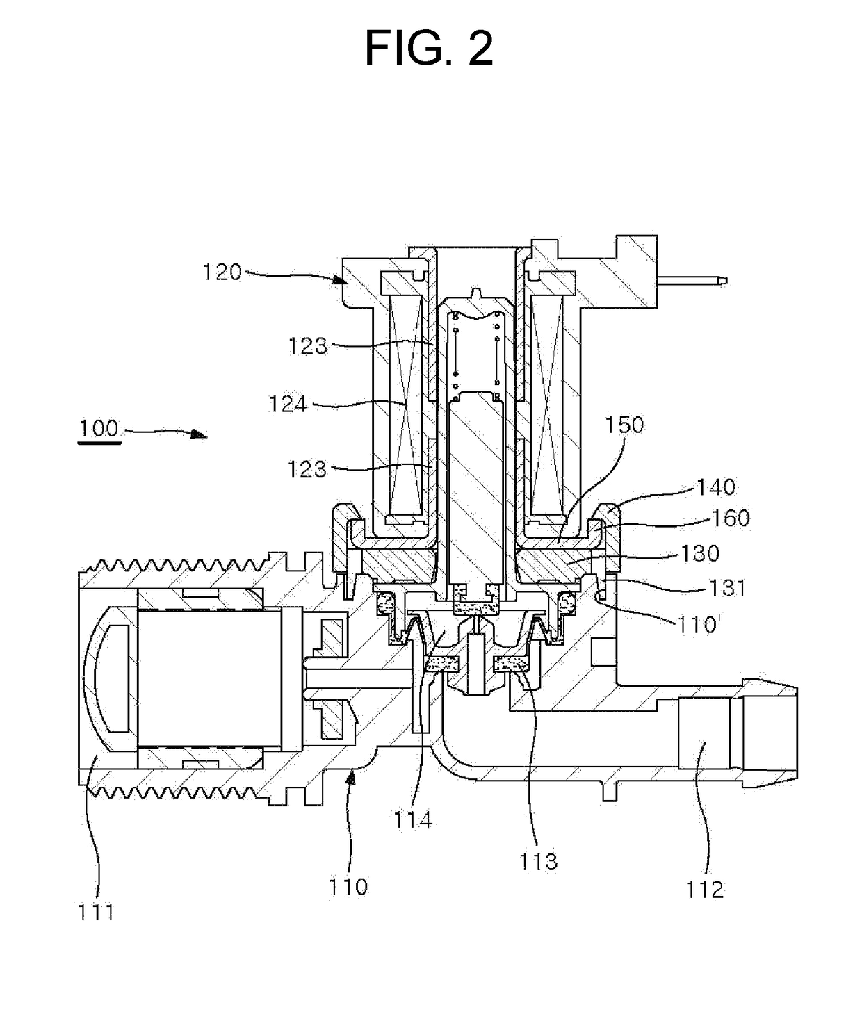
[0021]FIG. 1 is an exploded perspective view of the present invention. FIG. 2 is a cross-sectional view of the present invention.
[0022]According to the exemplary embodiment of the present invention, a coupling structure of an electromagnetic valve for controlling water supply, the electromagnetic valve including:
[0023]a valve body 110 provided with an inlet port 111 and an outlet port 112 through which water is respectively introduced and discharged, and a diaphragm 113 between the inlet port 111 and the outlet port 112 to define a pressure chamber 114; and an electromagnetic part 120 fixed on the valve body 110 to seal the pressure chamber 114, wherein the water is introduced into the pressure chamber 114 or discharged to a target device in response to operation of the electromagnetic part 120, thereby controlling water supply, the coupling str...
PUM
 Abstract
Description
Claims
Application Information