Electrically variable transmission having three planetary gear sets, a stationary member and three fixed interconnections

a technology of electric variable transmission and stationary member, which is applied in the direction of electric propulsion mounting, gearing, transportation and packaging, etc., can solve the problems of increasing fuel consumption and emissions beyond the ideal case, reducing the service life of the series electric drive, and reducing the service life of the electric drive. , to achieve the effect of improving fuel economy, improving vehicle acceleration performance, and best possible energy efficiency and emissions

Active Publication Date: 2007-08-23
GM GLOBAL TECH OPERATIONS LLC
View PDF7 Cites 52 Cited by
  • Summary
  • Abstract
  • Description
  • Claims
  • Application Information

AI Technical Summary

Benefits of technology

[0014] The present invention provides a family of electrically variable transmissions offering several advantages over conventional automatic transmissions for use in hybrid vehicles, including improved vehicle acceleration performance, improved fuel economy via regenerative braking and electric-only idling and launch, and an attractive marketing feature. An object of the invention is to provide the best possible energy efficiency and emissions for a given engine. In addition, optimal performance, capacity, package size, and ratio coverage for the transmission are sought.

Problems solved by technology

The wide variation in the demands that vehicles typically place on internal combustion engines increases fuel consumption and emissions beyond the ideal case for such engines.
A series electric drive suffers from the weight and cost of sufficient electric machinery to transform all of the engine power from mechanical to electrical in the generator and from electrical to mechanical in the drive motor, and from the useful energy lost in these conversions.

Method used


Image

  • Electrically variable transmission having three planetary gear sets, a stationary member and three fixed interconnections
  • Electrically variable transmission having three planetary gear sets, a stationary member and three fixed interconnections
  • Electrically variable transmission having three planetary gear sets, a stationary member and three fixed interconnections

Examples


second exemplary embodiment

Description of a Second Exemplary Embodiment

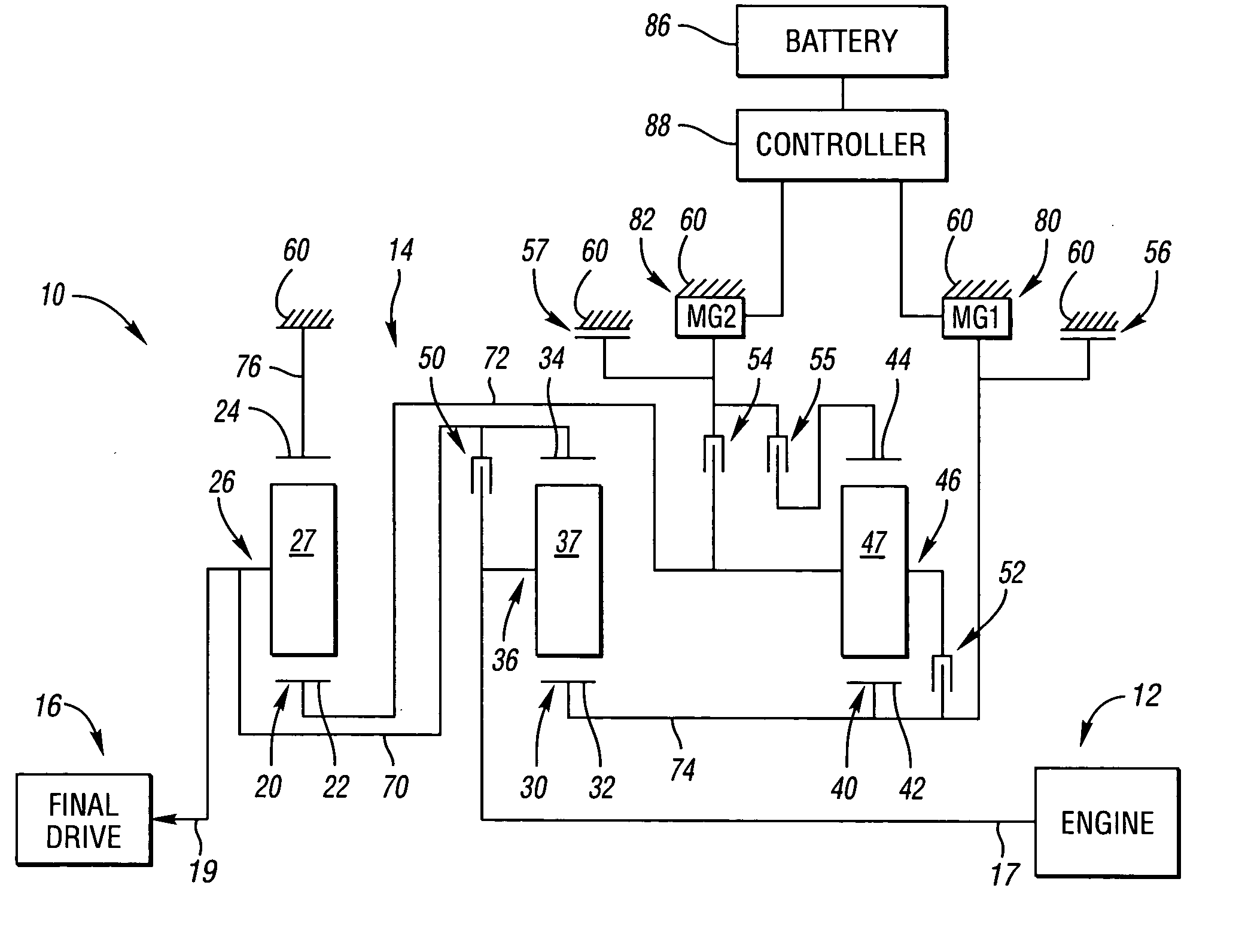
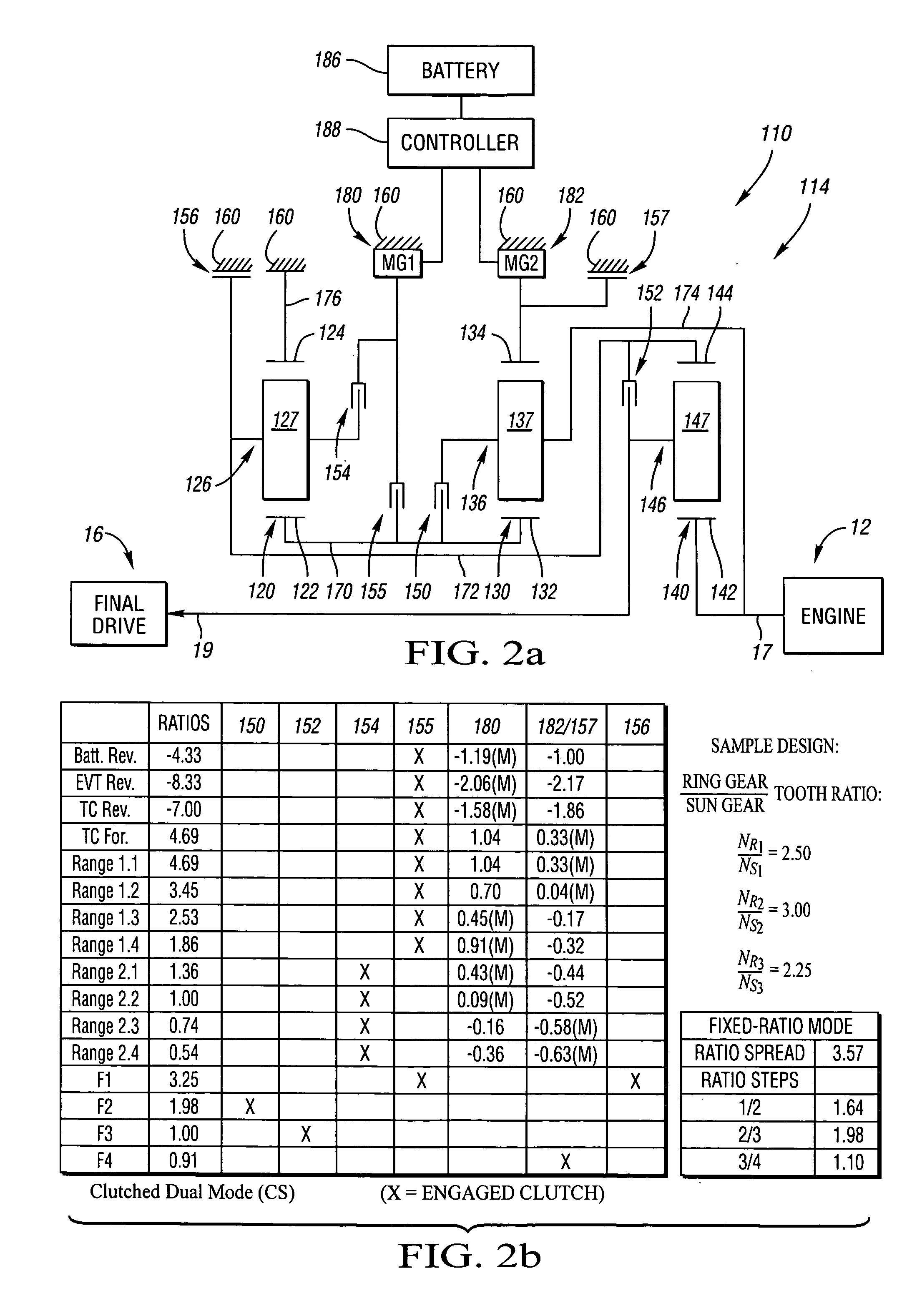
[0098] With reference to FIG. 2a, a powertrain 110 is shown, including an engine 12 connected to one preferred embodiment of the improved electrically variable transmission, designated generally by the numeral 114. Transmission 114 is designed to receive at least a portion of its driving power from the engine 12.

[0099] In the embodiment depicted the engine 12 may also be a fossil fuel engine, such as a diesel engine which is readily adapted to provide its available power output typically delivered at a constant number of revolutions per minute (RPM). As shown, the engine 12 has an output shaft that serves as the input member 17 of the transmission 14. A transient torque damper (not shown) may also be implemented between the engine 12 and the input member 17 of the transmission.

[0100] Irrespective of the means by which the engine 12 is connected to the transmission input member 17, the transmission input member 17 is operatively connected...

third exemplary embodiment

Description of a Third Exemplary Embodiment

[0115] With reference to FIG. 3a, a powertrain 210 is shown, including an engine 12 connected to one preferred embodiment of the improved electrically variable transmission, designated generally by the numeral 214. The transmission 214 is designed to receive at least a portion of its driving power from the engine 12. As shown, the engine 12 has an output shaft that serves as the input member 17 of the transmission 214. A transient torque damper (not shown) may also be implemented between the engine 12 and the input member 17 of the transmission 214.

[0116] Irrespective of the means by which the engine 12 is connected to the transmission input member 17, the transmission input member is operatively connected to a planetary gear set in the transmission 214. An output member 19 of the transmission 214 is connected to a final drive 16.

[0117] The transmission 214 utilizes three differential gear sets, preferably in the nature of planetary gear ...

fourth exemplary embodiment

Description of a Fourth Exemplary Embodiment

[0126] With reference to FIG. 4a, a powertrain 310 is shown, including an engine 12 connected to one preferred embodiment of the improved electrically variable transmission, designated generally by the numeral 314. The transmission 314 is designed to receive at least a portion of its driving power from the engine 12.

[0127] As shown, the engine 12 has an output shaft that serves as the input member 17 of the transmission 314. A transient torque damper (not shown) may also be implemented between the engine 12 and the input member 17 of the transmission.

[0128] Irrespective of the means by which the engine 12 is connected to the transmission input member 17, the transmission input member 17 is operatively connected to a planetary gear set in the transmission 314. An output member 19 of the transmission 314 is connected to a final drive 16.

[0129] The transmission 314 utilizes three planetary gear sets 320, 330 and 340. The planetary gear set...


PUM


Abstract

The electrically variable transmission family of the present invention provides low-content, low-cost electrically variable transmission mechanisms including first, second and third differential gear sets, a battery, two electric machines serving interchangeably as motors or generators, up to six selectable torque-transfer devices, and possibly a dog clutch. The selectable torque transfer devices are engaged to yield an EVT with a continuously variable range of speeds (including reverse) and mechanically fixed forward speed ratios. The torque transfer devices and the first and second motor/generators are operable to provide five operating modes in the electrically variable transmission, including battery reverse mode, EVT reverse mode, reverse and forward launch modes, continuously variable transmission range mode, and fixed ratio mode.

Description

TECHNICAL FIELD [0001] The present invention relates to electrically variable transmissions with selective operation both in power-split variable speed ratio ranges and in fixed speed ratios, and having three planetary gear sets, two motor / generators and up to six torque transfer devices. BACKGROUND OF THE INVENTION [0002] Internal combustion engines, particularly those of the reciprocating piston type, currently propel most vehicles. Such engines are relatively efficient, compact, lightweight, and inexpensive mechanisms by which to convert highly concentrated energy in the form of fuel into useful mechanical power. A novel transmission system, which can be used with internal combustion engines and which can reduce fuel consumption and the emissions of pollutants, may be of great benefit to the public. [0003] The wide variation in the demands that vehicles typically place on internal combustion engines increases fuel consumption and emissions beyond the ideal case for such engines. ...

Claims


Application Information

Patent Timeline
Patent Type & Authority Applications(United States)
IPC IPC(8): F16H3/72
CPCB60K1/02Y02T10/6239B60K6/40B60K6/445B60K6/547F16H3/728F16H2037/0866F16H2037/102F16H2037/104F16H2037/106F16H2200/0034F16H2200/0043F16H2200/201F16H2200/2035F16H2200/2041F16H2200/2043F16H2200/2046F16H2200/2097B60K6/365Y02T10/62
Inventor RAGHAVAN, MADHUSUDANBUCKNOR, NORMAN K.
Owner GM GLOBAL TECH OPERATIONS LLC
Why Eureka
Try Eureka