Paper food container with injection molded top rim structure and method of manufacturing same

Inactive Publication Date: 2007-09-13
MAZZAROLO IVONIS
View PDF12 Cites 8 Cited by
  • Summary
  • Abstract
  • Description
  • Claims
  • Application Information

AI Technical Summary

Benefits of technology

[0003] According to the first aspect of the present invention, an article of manufacture is provided in the form of a cup-shaped paper container having an open top, an injection molded plastic rim to receive a heat sealable cover of foil or other flexible, heat sealable membrane, and means for enhancing the mechanical adherence of the rim to the paper cup. The molded plastic rim structure is designed to provide a substantially flat, ring-shaped or annular upper surface which is capable of receiving in adhering relationship an impermeable covering material such as a metal foil with an under layer of heat sealable plastic.

Problems solved by technology

However, the price of plastic used to manufacture such containers is closely tied to the price of oil which, for a number of years has seen a steady upward trend.
A problem with the use of paper is the attachment of a heat sealable foil cover to the container.
Paper alone does not provide this.

Method used


Image

  • Paper food container with injection molded top rim structure and method of manufacturing same
  • Paper food container with injection molded top rim structure and method of manufacturing same
  • Paper food container with injection molded top rim structure and method of manufacturing same

Examples


first embodiment

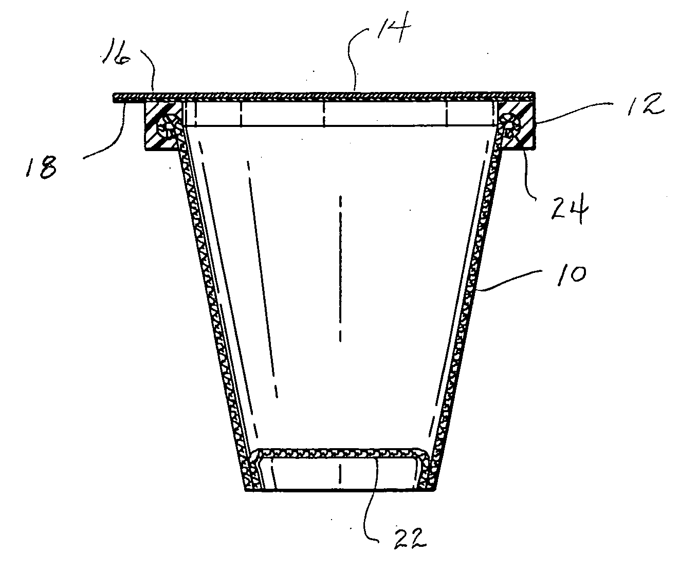
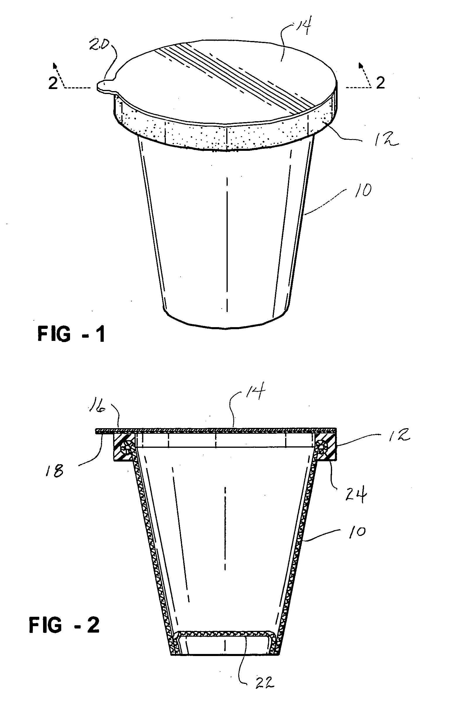
[0016] the upper edge of the container 10 is tightly rolled at 24. The manufacturing steps and equipment used to produce an article as thus far described are conventional and well known. In this embodiment, the rolled edge 24 acts as a means for enhancing the attachment of the rim structure 12.

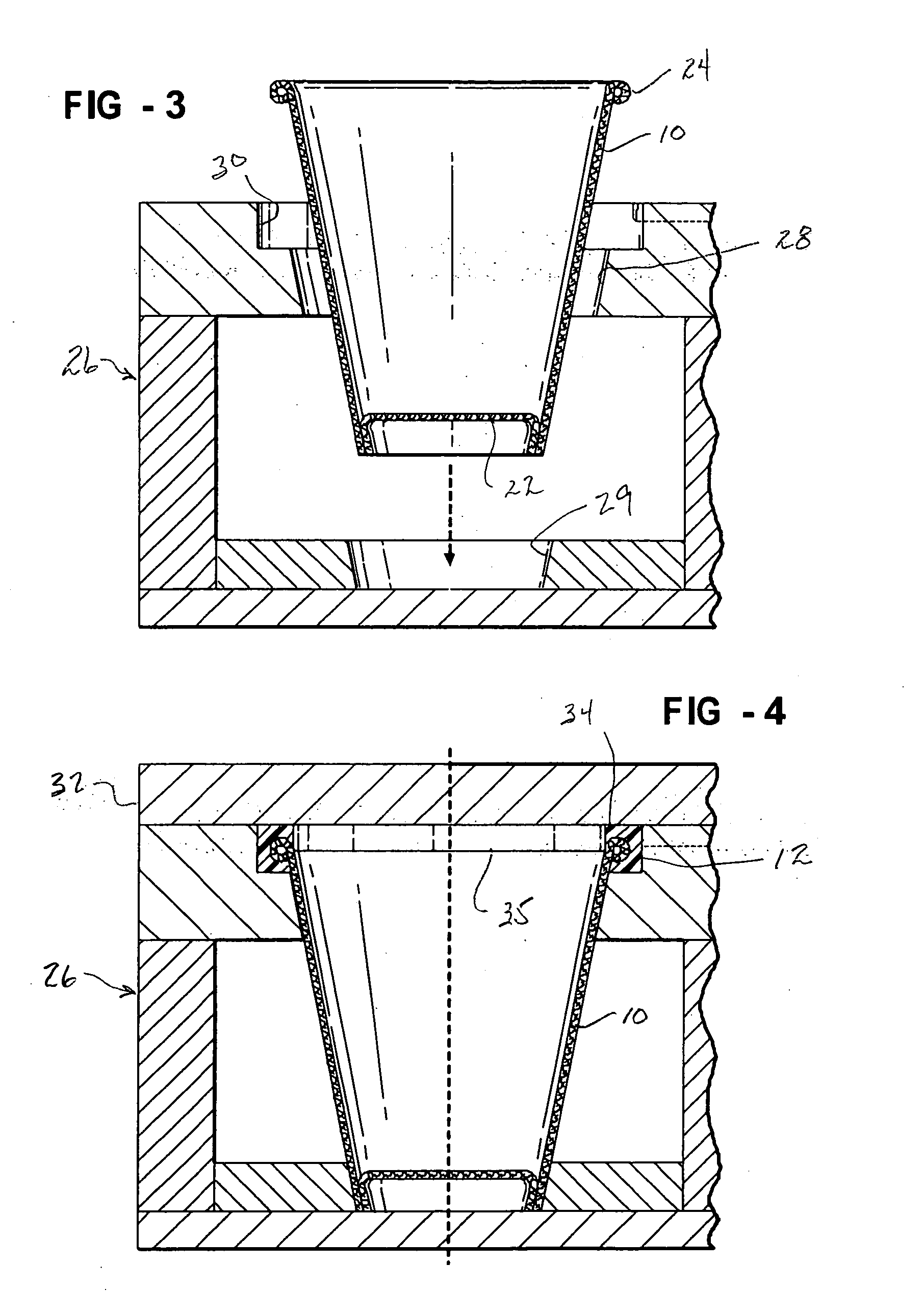
[0017] Referring now to FIGS. 3, 4 and 5, the additional steps needed to convert the paper cup 10 into a food product container in accordance with the present invention will be described. As shown in FIG. 3, a suitable injection molding apparatus 26 capable of withstanding high pressure conditions is shown to comprise tapered support surfaces 28 and 29 sized and shaped to receive and support the cup-shaped paper container 10 therein. When fully inserted, the rolled rim 24 of the paper container lies within an annular upper cavity 30 in spaced relationship with all surfaces thereof.

[0018] Turning now to FIG. 4, the mold 26 is closed by adding a high pressure cover 32. A plug 35 attached to th...

second embodiment

[0021] Referring now to FIGS. 7 and 8, the invention will be described. In this embodiment, a paper cup 10′ is constructed according to the description above except for the fact that the top edge is not rolled. Instead, a plurality of circumferentially spaced holes 42 are formed in the paper sidewall about ⅛ of an inch below the upper edge 44. The holes are preferably formed in the paper blank before it is rolled into the cup shape. The cup is inserted into a mold similar to that shown in FIGS. 3-5 and a rim structure 12′ having a flat annular top 48 is injection molded to the top of the cup 10 such that injected plastic flows into the holes 42 to form plugs 50 which enhance the mechanical attachment of the rim 12′ to the paper cup 10. In this embodiment, the edge 44 is not rolled. However, both the rolled rim 24 and the holes 42 may be used in combination if desired.

[0022] After the article shown in either FIG. 5 or FIG. 8 is manufactured, it is shipped to food processor who fills ...


PUM

PropertyMeasurementUnit
Mechanical propertiesaaaaaaaaaa
Impermeabilityaaaaaaaaaa

Abstract

A food container in the form of a paper cup having a top edge and a plastic rim structure which is injection molded to the edge so as to firmly be adhered thereto. The rim structure exhibits a flat annular upper surface to which a heat sealable closure made of metal foil with heat sealable plastic underlayer can be attached after filling the container with a suitable food product. The mechanical attachment between the rim and cup is enhanced either by rolling the top edge prior to the molding steps, or forming holes in the cup just below the top edge in the paper blank.

Description

FIELD OF THE INVENTION [0001] This invention relates to food containers and more particularly to a cup-shaped paper container having an open top and a plastic rim structure which is injection molded in adhering and encapsulating relationship to the container sidewall at the top edge so as to be capable of receiving in sealed relationship therewith a heat sealable cover. The invention also relates to a method of manufacturing such an article and a method of packaging food using such an article. BACKGROUND OF THE INVENTION [0002] It is known to provide food products such as yogurt in plastic containers having sealed foil covers. However, the price of plastic used to manufacture such containers is closely tied to the price of oil which, for a number of years has seen a steady upward trend. It is therefore desirable to use paper containers provided they can meet the requirements associated with the packaging of food products. A problem with the use of paper is the attachment of a heat s...

Claims


Application Information

Patent Timeline
IPC IPC(8): B65D1/42
CPCB29C45/14336B29C2045/0086B65D15/08B29L2031/7132B29K2711/12
Inventor MAZZAROLO, IVONIS
Owner MAZZAROLO IVONIS
Why Eureka
Try Eureka