Inductive power transfer system for underwater applications

Inactive Publication Date: 2008-01-03
COULSON ROBERT +2
View PDF2 Cites 25 Cited by
  • Summary
  • Abstract
  • Description
  • Claims
  • Application Information

AI Technical Summary

Benefits of technology

[0007] This invention relates to a power transfer system usable with an underwater system, such as, but not limited to, an autonomous underwater vehicle. In one embodiment, the autonomous underwater vehicle may be an unmanned, untethered submarine that provides marine researchers with a simple, long-range and low-cost mechanism for gathering oceanographic data. The power transfer system may be configured to facilitate the transfer of power from a docking station to the underwater vehicle while in water, such as an ocean or other water body. The power transfer system may be particularly suited for use in saltwater where conventional systems have failed. The power transfer system may be configured such that power may be transmitted between the docking station and the underwater vehicle without necessitating physical contact between connectors. Rather, the power transfer system may include a plurality of transformers used to transmit power via inductance. Thus, the power transfer system overcomes the fouling and marine growth issues common in saltwater environments.
[0009] In one embodiment, the first pair of transformers form a generally linear configuration. When the probe is inserted into the probe receiving chamber, gaps are formed from each side of the probe between the probe receiving chamber. The total distance of a sum of a first distance between the first and third partial transformers and a second distance between the second and fourth partial transformers may be less than about 0.1 inch. As the probe moves from side to side in the probe receiving chamber, the effective average gap remains constant because as one gap grows, the other gap shrinks. This constant effective average gap keeps that leakage inductance relatively constant, which enables a fixed value capacitor to be used to cancel out the leakage inductance at a given frequency. Canceling the leakage inductance greatly increases the amount of power that may be transferred.
[0012] An advantage of this invention is that the configuration of the partial transformers in the probe and in the wall forming the probe receiving chamber enables the average effective gap to remain constant, thereby keeping the leakage inductance relatively constant. Keeping the leakage inductance constant permits a capacitor with a fixed value to be used to cancel out the leakage inductance at a particular frequency. Canceling the leakage inductance greatly increases the amount of power transfer capable of being transferred by the system. Such increased power transfer increases the available power supply to the underwater vehicle, thereby increasing the options available to the system.
[0013] Another advantage of this system is that the power may be transferred to the power system of the underwater vehicle without physical contact occurring between electrical elements in the probe and in the underwater vehicle, thereby overcoming the problems associated with fouling, marine growth, stray currents and corrosion.
[0014] Yet another advantage of this system is that the probe may be also be used as an anchor to lock the underwater vehicle into position in relation to the docking station. Doing so not only retains the vehicle securely in the dock without the need to a secondary capture actuator, but also allows for the accurate alignment of multiple RF communications patch antenna establishing a high speed data link between the vehicle payload and the dock station.

Problems solved by technology

Canceling the leakage inductance greatly increases the amount of power that may be transferred.

Method used


Image

  • Inductive power transfer system for underwater applications
  • Inductive power transfer system for underwater applications
  • Inductive power transfer system for underwater applications

Examples


Embodiment Construction

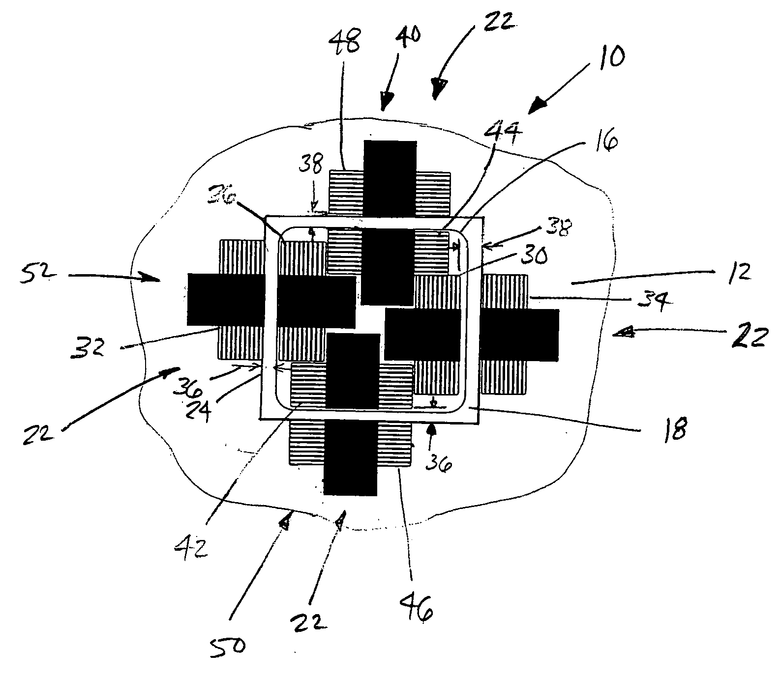
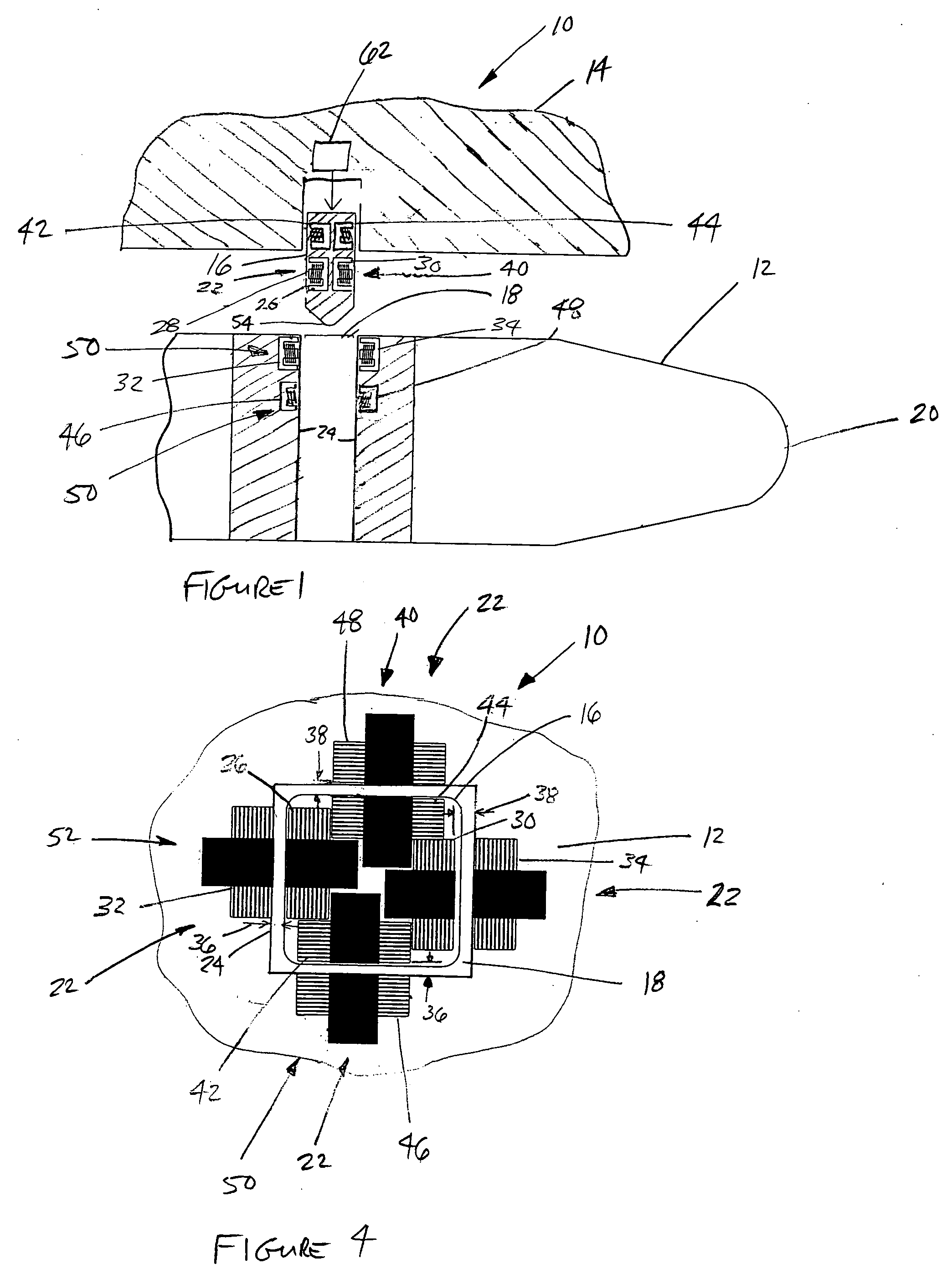
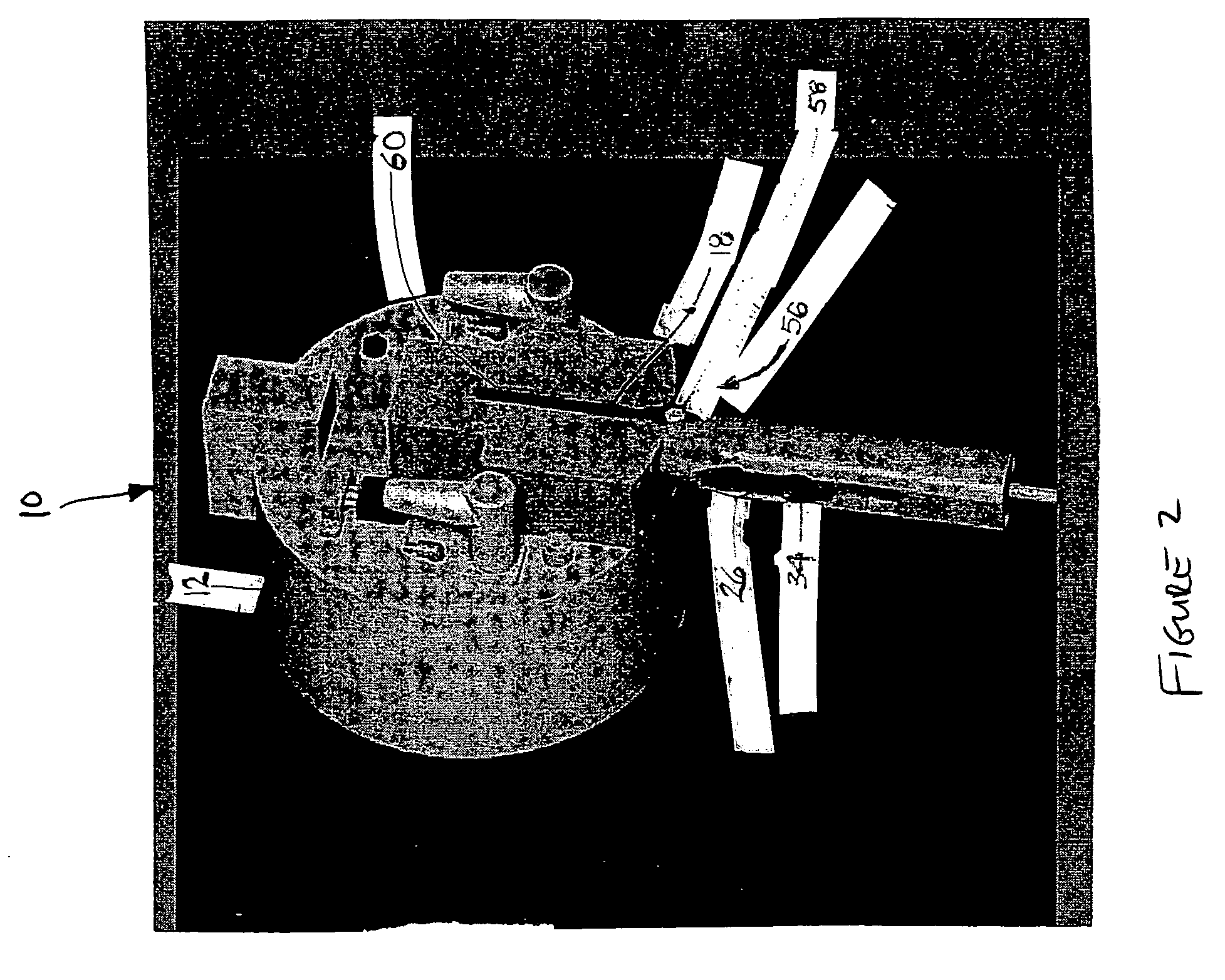
[0024] As shown in FIGS. 1-7, this invention is directed to a power transfer system 10 usable with an underwater system 12, such as, but not limited to, an autonomous underwater vehicle 12. In one embodiment, the autonomous underwater system 12 may be an unmanned, untethered submarine that provides marine researchers with a simple, long-range and low-cost mechanism for gathering oceanographic data. The power transfer system 10 is configured to facilitate the transfer of power from a docking station 14 to the underwater vehicle 12 while in water, such as an ocean or other water body. The power transfer system 10 is particularly suited for use in saltwater where conventional systems have failed but may be used in other water types as well. The power transfer system 10 has been configured such that power may be transmitted between the docking station 14 and the underwater vehicle 12 without necessitating physical contact between connectors. Rather, the power transfer system 10 includes...


PUM


Abstract

An underwater inductive power transfer system enabling power to be transferred from a docking station to another underwater system without direct physical electrical contact between conductors. The power transfer system may include a probe configured to be inserted into a probe receiving chamber. The probe may include a plurality of partial transformers positioned to be aligned with a plurality of transformers proximate to a surface forming a probe receiving chamber. The probe may include partial transformers positioned on opposite sides of the probe, and the prove receiving cavity may include partial transformers positioned on opposite sides of the cavity. The probe receiving chamber may be sized such that the partial transformers in the probe may be positioned in close proximity to the partial transformers in the sidewalls forming the probe receiving chamber so that power may be transmitted between the transformers.

Description

CROSS-REFERENCE TO RELATED APPLICATIONS [0001] This application claims the benefit of U.S. Provisional Patent Application Ser. No. 60 / 727,317 filed Oct. 17, 2005.STATEMENT REGARDING FEDERALLY FUNDED RESEARCH [0002] The U.S. Government has a paid-up license in this invention and the right in limited circumstances to require the patent owner to license others on reasonable terms as provided for by the terms of N0014-98-1-0861 awarded by the Office of Naval Research.FIELD OF THE INVENTION [0003] This invention is directed generally to inductive power transfer systems, and more particularly to power transfer between underwater systems, such as for underwater vehicles. BACKGROUND [0004] Underwater vehicles have proven useful for scientists, researchers, underwater recover efforts and other endeavors. One particular type of underwater vehicles, autonomous underwater vehicles (AUVs), are unmanned and untethered submarines that provide researchers with a simple, long-range and cost effectiv...

Claims


Application Information

Patent Timeline
IPC IPC(8): H01F21/04
CPCB63G8/001B63G2008/004H01F2038/143H01F38/14B63G2008/008
Inventor COULSON, ROBERTLAMBIOTTE, JOEPANTELAKIS, TOM
Owner COULSON ROBERT
Why Eureka
Try Eureka