Planar Speaker Driver

a speaker driver and plane technology, applied in the field of acoustic devices, can solve the problems of limited low frequency extension, large diaphragm with much less vibration control, and generate significant modal vibration, and achieve the effects of reducing noise and driver structural resonance, reducing operating frequency band, and high efficiency

Active Publication Date: 2008-03-20
CHRISTIE DIGITAL SYST USA INC
View PDF60 Cites 6 Cited by
  • Summary
  • Abstract
  • Description
  • Claims
  • Application Information

AI Technical Summary

Benefits of technology

[0013]A planar transducer with extended low frequency operational band and high efficiency is disclosed. In one aspect the planar transducer has top and bottom plates that are maintained in a curved (buckled) or arcuate shape due to mechanical tension placed across their surfaces. In one embodiment, plates are dimensioned so that the repellant magnetic force induced by the opposing the attached magnets is sufficient to push the plates away from each other and maintain them under the necessary tension and curvature. This aspect reduces noise and driver structural resonance.

Problems solved by technology

Among performance limitations traditionally associated with planar drivers are limited low frequency extension and limited dynamic range at those frequencies.
Both of these issues are mostly related to two aspects of driver design and operation: maximum diaphragm excursion capability and vibration behavior of the diaphragm within the operating range.
However, a larger diaphragm has much less vibration control and generates significant modal vibrations due to insufficient mechanical losses in diaphragm substrate, usually plastic film.
These pronounced vibrations at diaphragm resonance frequencies lead to response irregularities and parasitic noises at lower frequencies that are very often encountered in planar transducers.
Both of these methods have negative effects.
A coating leads to higher mass and efficiency losses.
Corrugation of the entire diaphragm increases the effective thickness of the diaphragm where active conductions are located and thus limits maximum excursion of the diaphragm.
Additionally the corrugation of diaphragm in the area of active conductors that are made of very thin metal foil can introduce internal stresses in the conductor and / or in the bond between polymer film and the foil conductor.
Under high thermal and mechanical stress due to vibrations the internal stresses can then lead to premature de-lamination or cracks in the conductors.

Method used


Image

  • Planar Speaker Driver
  • Planar Speaker Driver
  • Planar Speaker Driver

Examples


Embodiment Construction

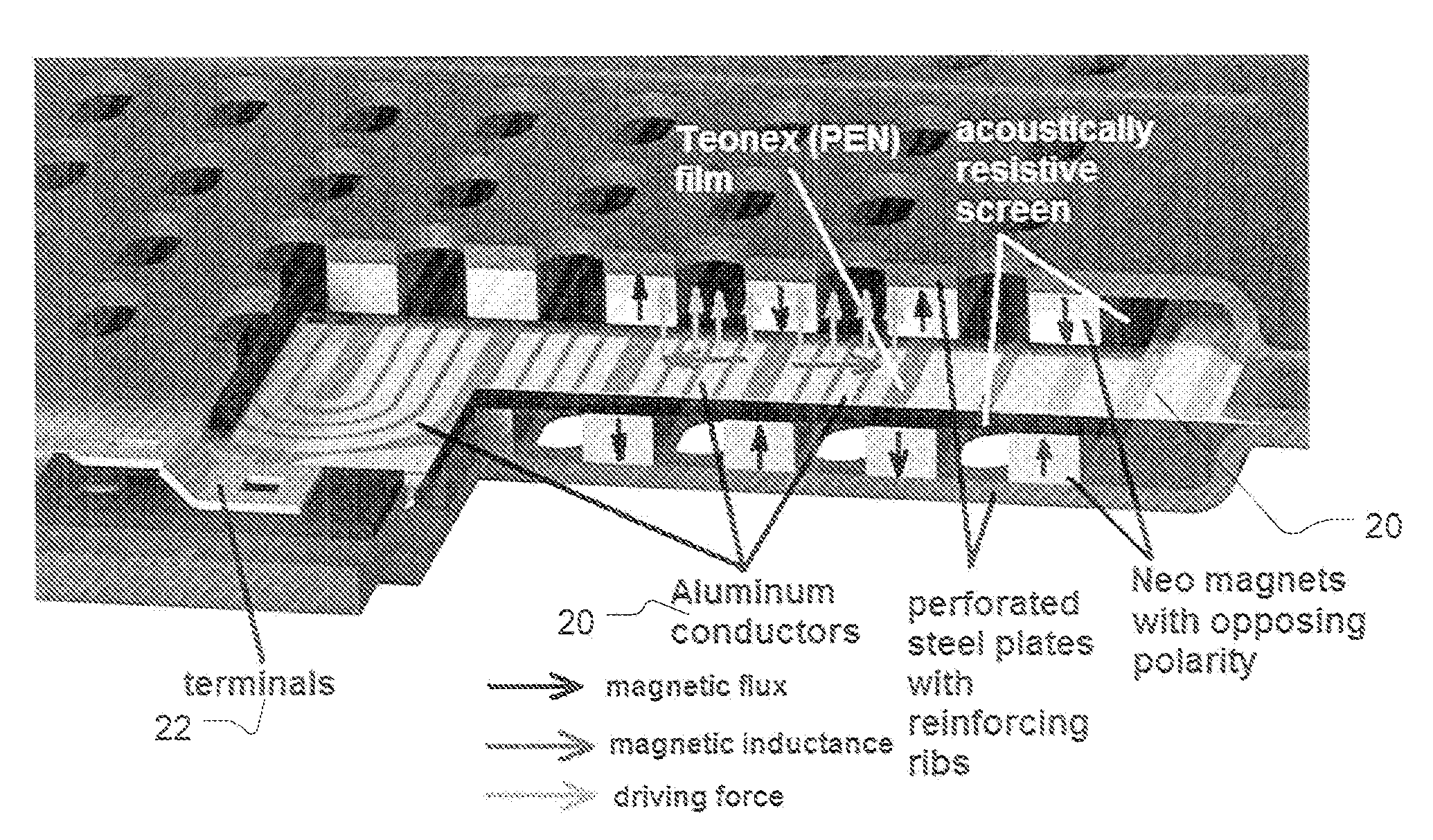
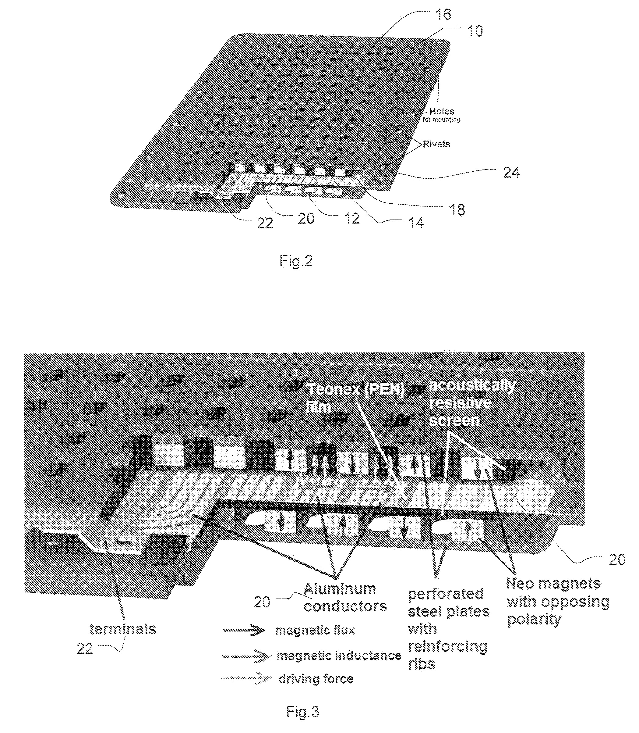
[0021]FIGS. 2-6 depict various views of embodiments of a planar driver showing various features of the present invention. FIG. 2 illustrates a perspective and cut-away view of planar driver in accordance with the present invention. FIG. 3 illustrates the cutaway portion of FIG. 2 in further detail, with force arrows showing the directions of magnetic force. Shown here are top and bottom plates 10 with attached magnets 12 on the interior facing surfaces of the plates, with diaphragm 14 disposed therebetween along the edges 24 of the plates 10. Holes 16 are disposed in the plates 10. The diaphragm 14 comprises a foil film 18 and conductors 20 (e.g., aluminium strips). A terminal 22 is coupled to the conductors 20 to provide electrical communication to a signal.

[0022]Generally, a clamped diaphragm does not vibrate as a piston. At lower frequencies especially at the fundamental resonance the amplitude of vibrations are much larger in the middle of diaphragm than at the periphery near cl...


PUM


Abstract

A planar magnetic driver includes covering plates that are maintained under tension to form a buckled or curved surface, thereby providing for a larger magnetic gap, and allowing for a larger excursion of the diaphragm and extended lower frequency response. Another aspect of the driver includes a corrugated region along the periphery of the diaphragm, which provides increased internal dampening.

Description

CROSS-REFERENCE TO RELATED APPLICATION[0001]This application claims priority from U.S. Provisional Application No. 60 / 825,690 entitled “Planar Speaker Driver” filed on Sep. 14, 2006, the content of which is incorporated by reference herein in its entirety.BACKGROUND[0002]1. Field of the Art[0003]The present invention generally relates to acoustic devices, and more specifically to a planar speaker driver.[0004]2. Description of the Related Art[0005]Planar (planar-magnetic, ribbon, thin film drivers) drivers have always been praised for exceptional sound quality associated with their unique acoustic attributes. This invention describes a wide-band planar transducer with high sensitivity, extended lower frequency operating band, higher power handling and low distortion.[0006]FIG. 1 illustrates a cross-section showing a basic construction of a typical planar-magnetic transducer. A common type of such transducer incorporates a diaphragm 1 with areas of multiple electrical conductors 2. A...

Claims


Application Information

Patent Timeline
Patent Type & Authority Applications(United States)
IPC IPC(8): H04R1/00
CPCH04R9/047H04R2307/207H04R2307/201
Inventor LEVITSKY, IGOR
Owner CHRISTIE DIGITAL SYST USA INC
Why Eureka
Try Eureka