Signal control circuit and signal control apparatus

a signal control circuit and signal control technology, applied in the direction of instruments, coding, code conversion, etc., can solve the problems of lowering the input or output speed, reducing the performance, and expensive power source and related circuit strengthening

Inactive Publication Date: 2008-07-03
SOCIONEXT INC
View PDF6 Cites 0 Cited by
  • Summary
  • Abstract
  • Description
  • Claims
  • Application Information

AI Technical Summary

Benefits of technology

[0009]According to an aspect of an embodiment, a signal control circuit for outputting data of a plurality of bits comprises a data generation block for generating the data of the plurality of bits, a data storage block for storing the data generated by the data generation block and outputting the data to an external circuit in response to a request for outputting the data; a data retention block for retaining data output in a preceding session; a data judgment block for judging the number of changed bits when the data is output from the data generation block, by comparing each bit of the data output in the preceding session and a corresponding bit of the data to be sent in

Problems solved by technology

In general signal control circuits included in large-scale-integration (LSI) chips, noise resulting from a concurrent change in a plurality of bits of an output signal (for example, an output signal of eight bits is changed from “00000000” to “11111111”) output from the si

Method used


Image

  • Signal control circuit and signal control apparatus
  • Signal control circuit and signal control apparatus
  • Signal control circuit and signal control apparatus

Examples


Embodiment Construction

[0026]An embodiment of the present invention will be described below with reference to the drawings.

[0027]An overview of the present invention will be described first, and then, the embodiment will be described.

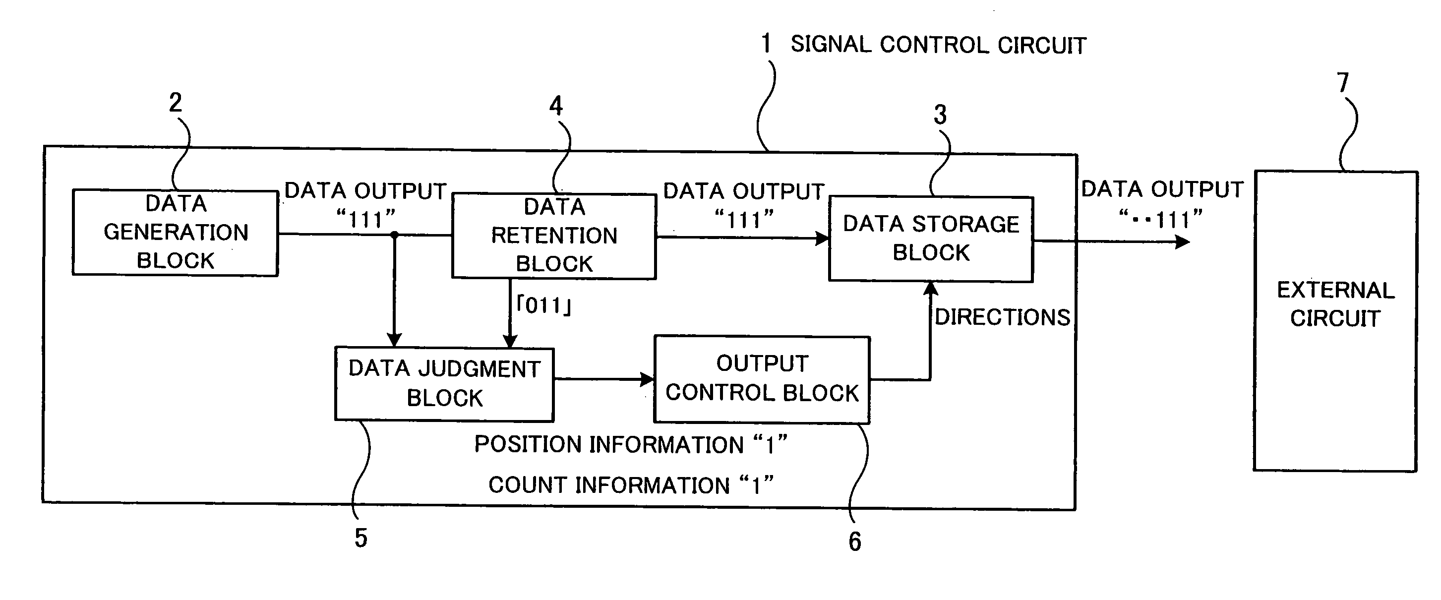
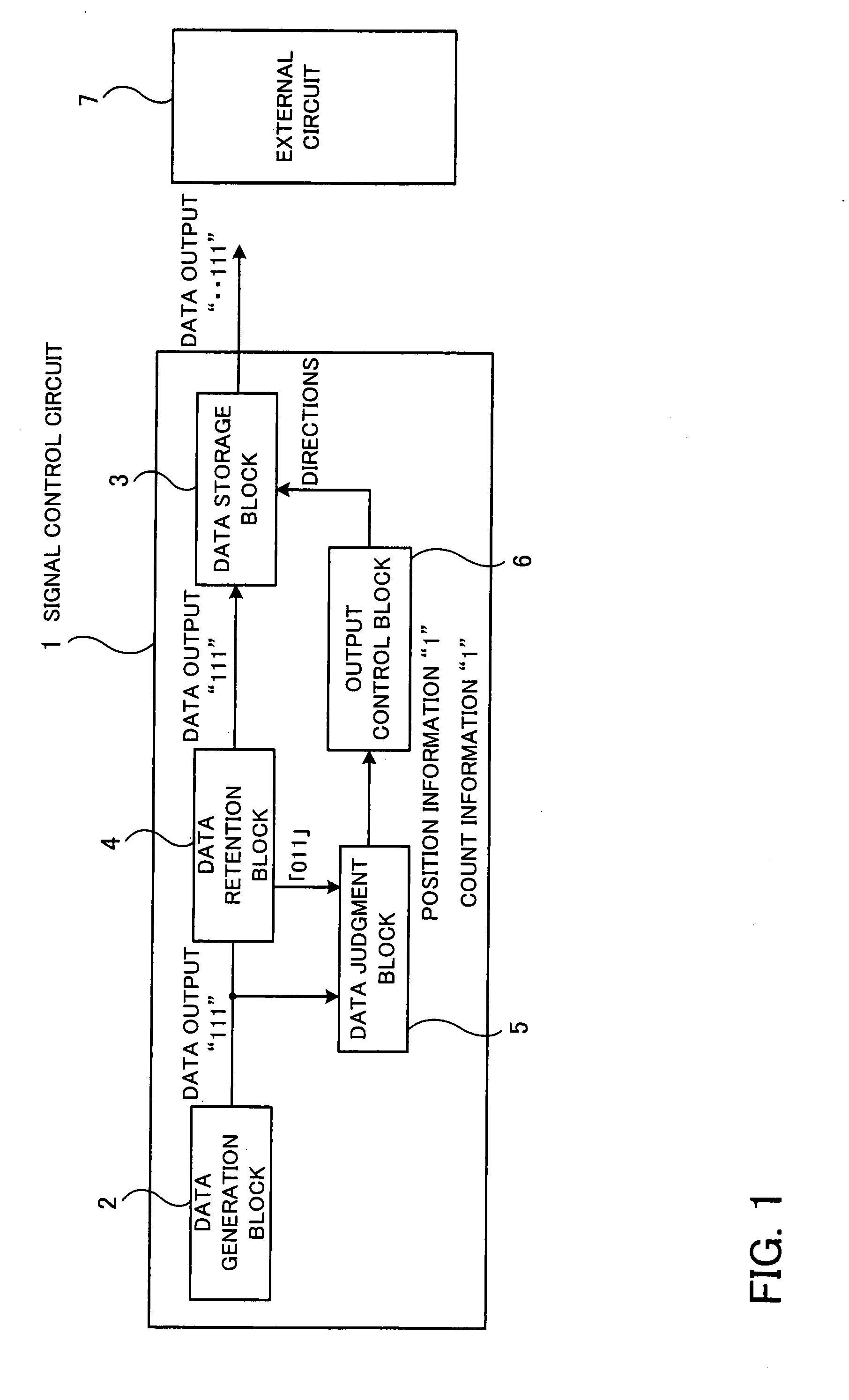
[0028]FIG. 1 is a view showing an overview of the present invention.

[0029]A signal control circuit 1 shown in FIG. 1 includes a data generation block 2, a data storage block 3, a data retention block 4, a data judgment block 5, and an output control block 6.

[0030]The data generation block 2 generates data of a plurality of bits (“111” in FIG. 1).

[0031]The data storage block 3 stores the data generated by the data generation block 2 and outputs the data to an external circuit 7 disposed outside the signal control circuit 1 in accordance with a request for outputting the data. The external circuit 7 is an external circuit viewed from the signal control circuit 1, and the signal control circuit 1 and the external circuit 7 may be formed integrally.

[0032]The data retention block ...


PUM


Abstract

A signal control circuit and a signal control apparatus that can reduce processing time and can send or receive correct data with reliability. When a data generation block outputs data, a data judgment block judges the number of changed bits by comparing each bit of the data output in the preceding session with the corresponding bit of the data to be sent in the current session and outputs position information indicating the position of each changed bit and the number of changed bits when the number of changed bits has reached a predetermined level. An output control block keeps a time period for stabilizing the change in value of the bit corresponding to the position information when the data is output, and directs a data storage block to send the value of the bit corresponding to the position information to an external circuit after the kept period has passed.

Description

CROSS-REFERENCE TO RELATED APPLICATIONS[0001]This application is based upon and claims the benefits of priority from the prior Japanese Patent Application No. 2006-354396 filed Dec. 28, 2006, the entire contents of which are incorporated herein by reference.BACKGROUND OF THE INVENTION[0002]1. Field of the Invention[0003]The present invention relates to signal control circuits and signal control apparatuses, and particularly to a signal control circuit having an external output terminal for a plurality of bits and a signal control apparatus for inputting and outputting data of a plurality of bits inside the apparatus.[0004]2. Description of the Related Art[0005]In general signal control circuits included in large-scale-integration (LSI) chips, noise resulting from a concurrent change in a plurality of bits of an output signal (for example, an output signal of eight bits is changed from “00000000” to “11111111”) output from the signal control circuit may cause one or more bits of the ...

Claims


Application Information

Patent Timeline
IPC IPC(8): G06F11/07G06F7/06
CPCG06F11/00
Inventor MINOSHIMA, HIROYUKI
Owner SOCIONEXT INC
Why Eureka
Try Eureka