Power converter with over temperature protection compensation

a technology power converter, which is applied in the direction of power conversion systems, dc-dc conversion, instruments, etc., can solve the problems of increasing the risk of damage to the power converter, and increasing the risk of over temperature protection compensation

Active Publication Date: 2020-08-06
CHICONY POWER TECH CO LTD
View PDF0 Cites 0 Cited by
  • Summary
  • Abstract
  • Description
  • Claims
  • Application Information

AI Technical Summary

Benefits of technology

[0022]In one embodiment, the compensation resistor includes a first compensation resistor and a second compensation resistor. The first compensation resistor is coupled to the primary-side control unit, the temperature control resistor, and the control unit. The second compensation resistor is coupled to the primary-side control unit, the temperature control resistor, and the control unit. The control unit controls the first compensation resistor in parallel or not in parallel with the second compensation resistor according to the control signal so as to adjust the resistance change value.

Problems solved by technology

This will cause the controller to delay activating the over temperature protection mechanism, thereby increasing the risk of damaging the power converter.
On the contrary, when the input voltage of the power converter is low, the conversion efficiency is poor, which causes more heat loss caused by energy conversion.
Therefore, in the above regulation and the input voltage of the power converter is high, or the output current is overloaded, it is easy to cause the power converter to actually be overloaded, but the over temperature protection mechanism has not been activated.
However, if the design is below this trigger point and the input voltage of the power converter is high, there is a large error from the trigger point of the actual over temperature protection mechanism, which makes the over temperature protection mechanism meaningless.

Method used


Image

  • Power converter with over temperature protection compensation
  • Power converter with over temperature protection compensation
  • Power converter with over temperature protection compensation

Examples


first embodiment

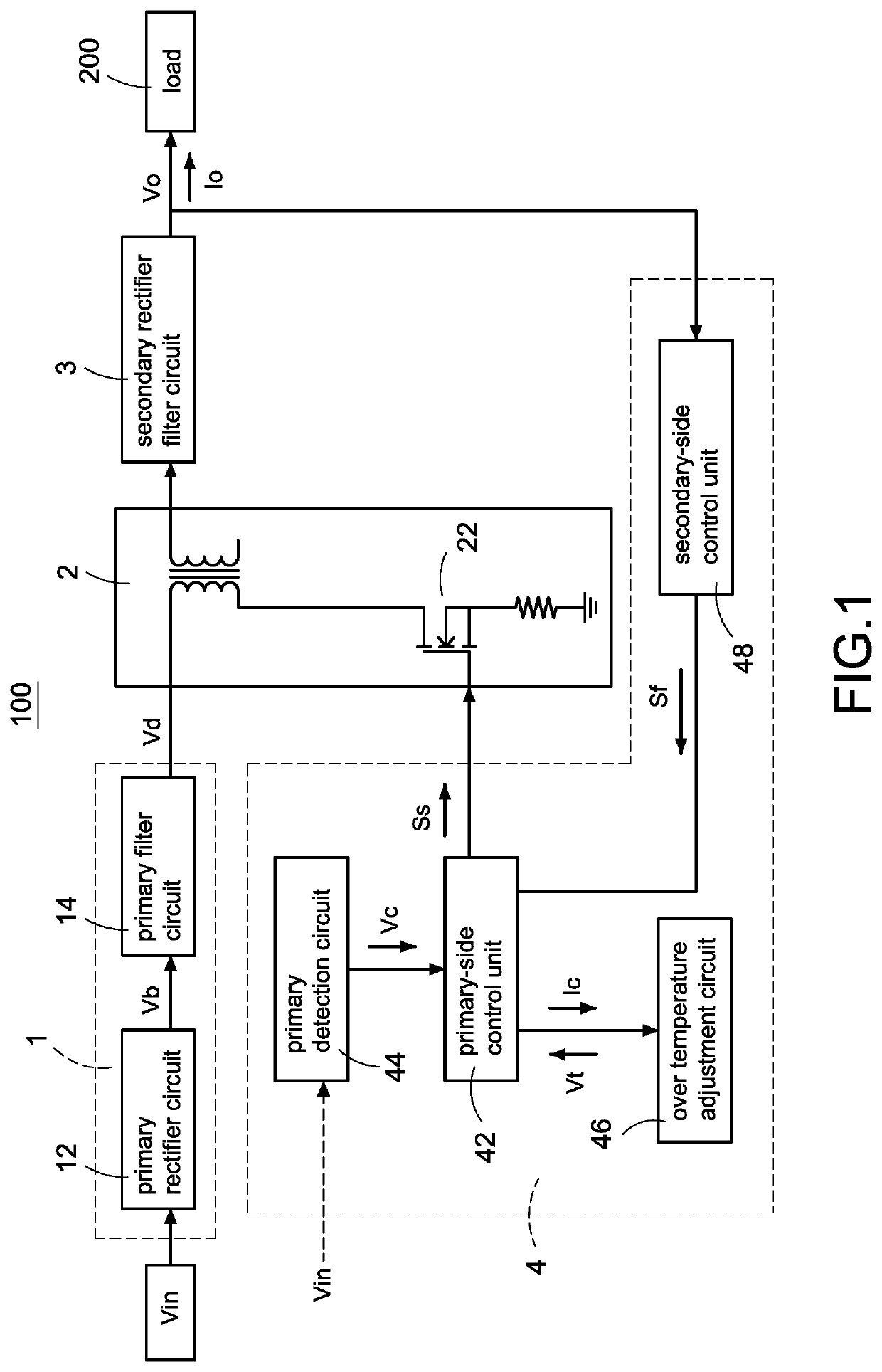
[0037]Please refer to FIG. 1, which shows a block circuit diagram of a power converter with over temperature protection compensation according to the present disclosure. The power converter 100 receives an input voltage Vin and converters the input voltage Vin into an output voltage Vo for supplying power to a load 200. The power converter 100 is a power converter 100 that accepts a wide input voltage Vin with an acceptable input voltage Vin ranging from 90 volts to 264 volts. The power converter 100 includes a primary rectifier filter circuit 1, a main conversion unit 2, a secondary rectifier filter circuit 3, and a control module 4. A primary side of the main conversion unit 2 is coupled to the primary rectifier filter circuit 1, and a secondary side of the main conversion unit 2 is coupled to the secondary rectifier filter circuit 3. The control module 4 controls the main conversion unit 2 to convert the input voltage Vin into the output voltage Vo through a path composed of the ...

second embodiment

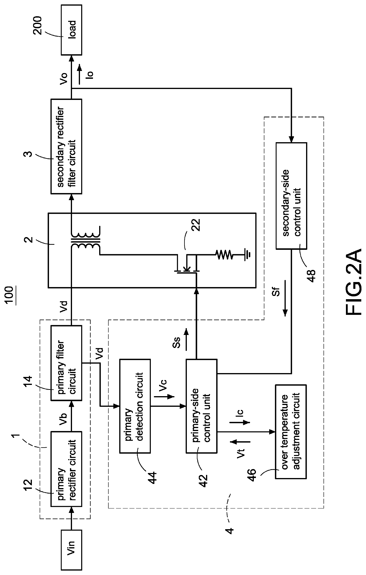
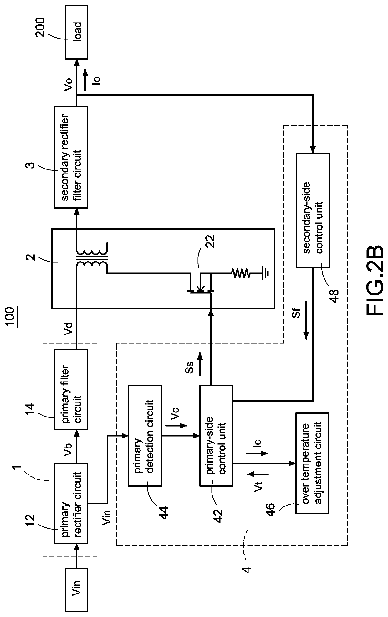
[0055]In one embodiment, the temperature compensation circuit 462 is not limited to the coupling manner as shown in FIG. 5, and may be coupled between the primary-side control unit 42′ and the temperature control resistor Rt, or between the temperature control resistor Rt and the ground point. In one embodiment, the unexplained circuit structure and control manner of the power converter 100′ according to FIG. 5 are the same as those of FIG. 1. The detection manner applicable to the primary voltage change value Vc of FIG. 2A to FIG. 2D and the internal structure of the primary detection circuit 44 are also applicable to the circuit structures of FIG. 3A to FIG. 3B, and will not be described again here.

[0056]Please refer to FIG. 6, which shows a block circuit diagram of a temperature compensation circuit according to the present disclosure, and also refer to FIG. 1 to FIG. 5. The temperature compensation circuit 462 includes a detection circuit 462A, a voltage control switch 462B, a c...


PUM


Abstract

A power converter with over temperature protection compensation includes a main conversion unit, a primary-side control unit, a primary detection circuit, and an over temperature adjustment circuit. The primary-side control unit obtains a primary voltage change value through the primary detection circuit, and the primary-side control unit correspondingly provides a current change value to the over temperature adjustment circuit according to the primary voltage change value. The over temperature adjustment circuit provides a temperature control voltage according to the current change value so that the primary-side control unit determines whether an over temperature protection is activated according to the temperature control voltage.

Description

BACKGROUNDTechnical Field[0001]The present disclosure relates to a power converter with over temperature protection compensation, and more particularly to a power converter with over temperature protection compensation disposed on a primary side of a conversion unit.Description of Related Art[0002]The statements in this section merely provide background information related to the present disclosure and do not necessarily constitute prior art.[0003]In the technical field of power converters, the over temperature protection (OTP) mechanism of the internal controller of the power converter has always been indispensable. However, no matter whether the input voltage of the power converter is low or high, the power converter must reach a fixed temperature or higher to activate (trigger) the over temperature protection. Therefore, when the input voltage of the power converter changes, the actual triggering point of the over temperature protection mechanism will be different. This will caus...

Claims


Application Information

Patent Timeline
Patent Type & Authority Applications(United States)
IPC IPC(8): H02M3/335H02M1/32
CPCH02M1/32H02M3/33507H02M2001/327H02H7/10H02M1/327
Inventor PENG, TSO-JENWANG, SSU-HAO
Owner CHICONY POWER TECH CO LTD
Why Eureka
Try Eureka