Heat Exchanger Plate and a Plate Package

a technology of heat exchanger plate and plate package, which is applied in indirect heat exchangers, laminated elements, light and heating apparatus, etc., can solve the problems of deteriorating affecting the efficiency of plate heat exchanger, and affecting the distribution area, so as to achieve the effect of improving the distribution area

Inactive Publication Date: 2008-09-18
ALFA LAVAL CORP AB
View PDF8 Cites 16 Cited by
  • Summary
  • Abstract
  • Description
  • Claims
  • Application Information

AI Technical Summary

Benefits of technology

[0008]The object of the present invention is to provide a heat exchanger plate intended f

Problems solved by technology

A disadvantage of such known distribution patterns is that they also contribute to a too large pressure drop over the distribution area.
Such a pressure drop deteriorates the efficiency of the plate

Method used


Image

  • Heat Exchanger Plate and a Plate Package
  • Heat Exchanger Plate and a Plate Package
  • Heat Exchanger Plate and a Plate Package

Examples


Embodiment Construction

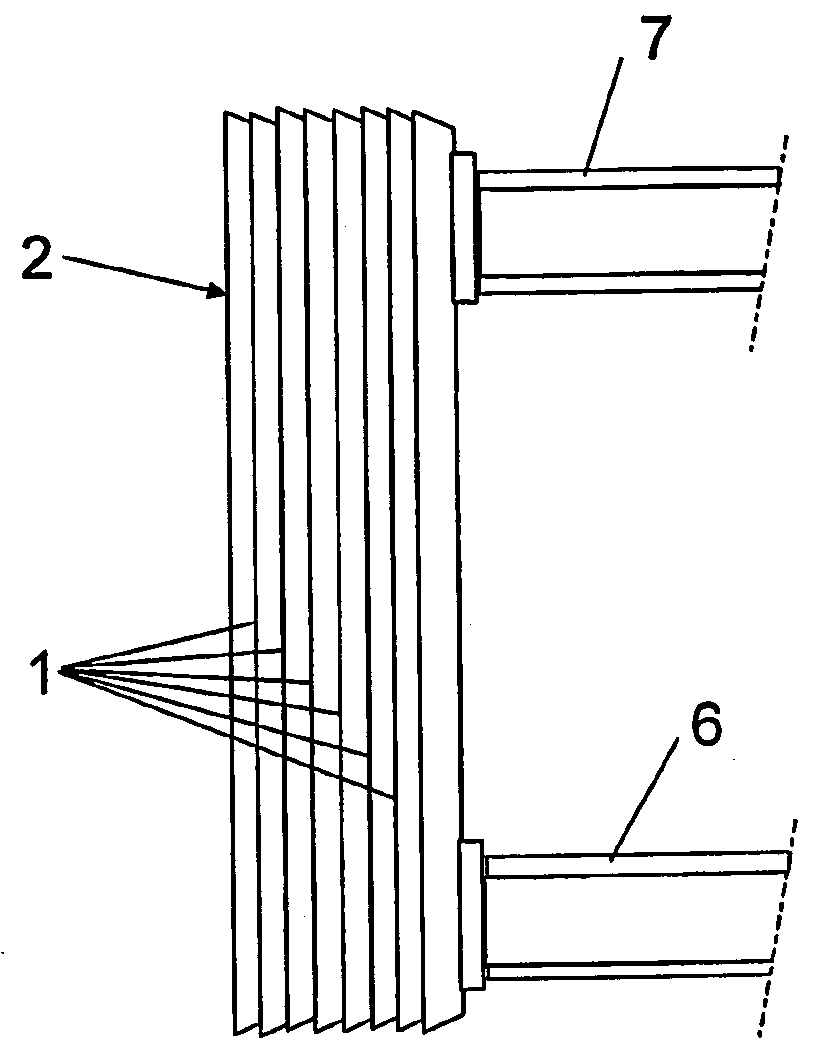
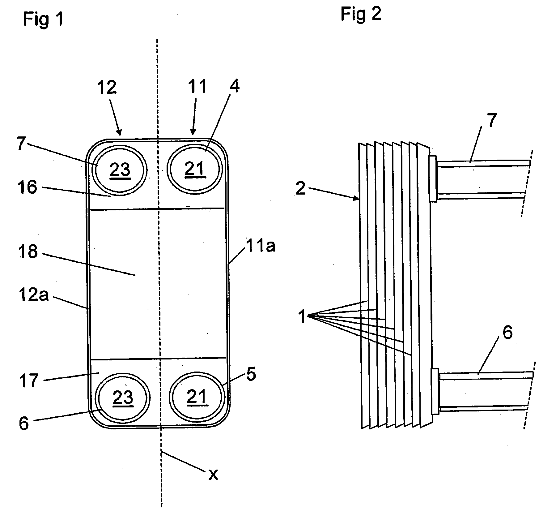
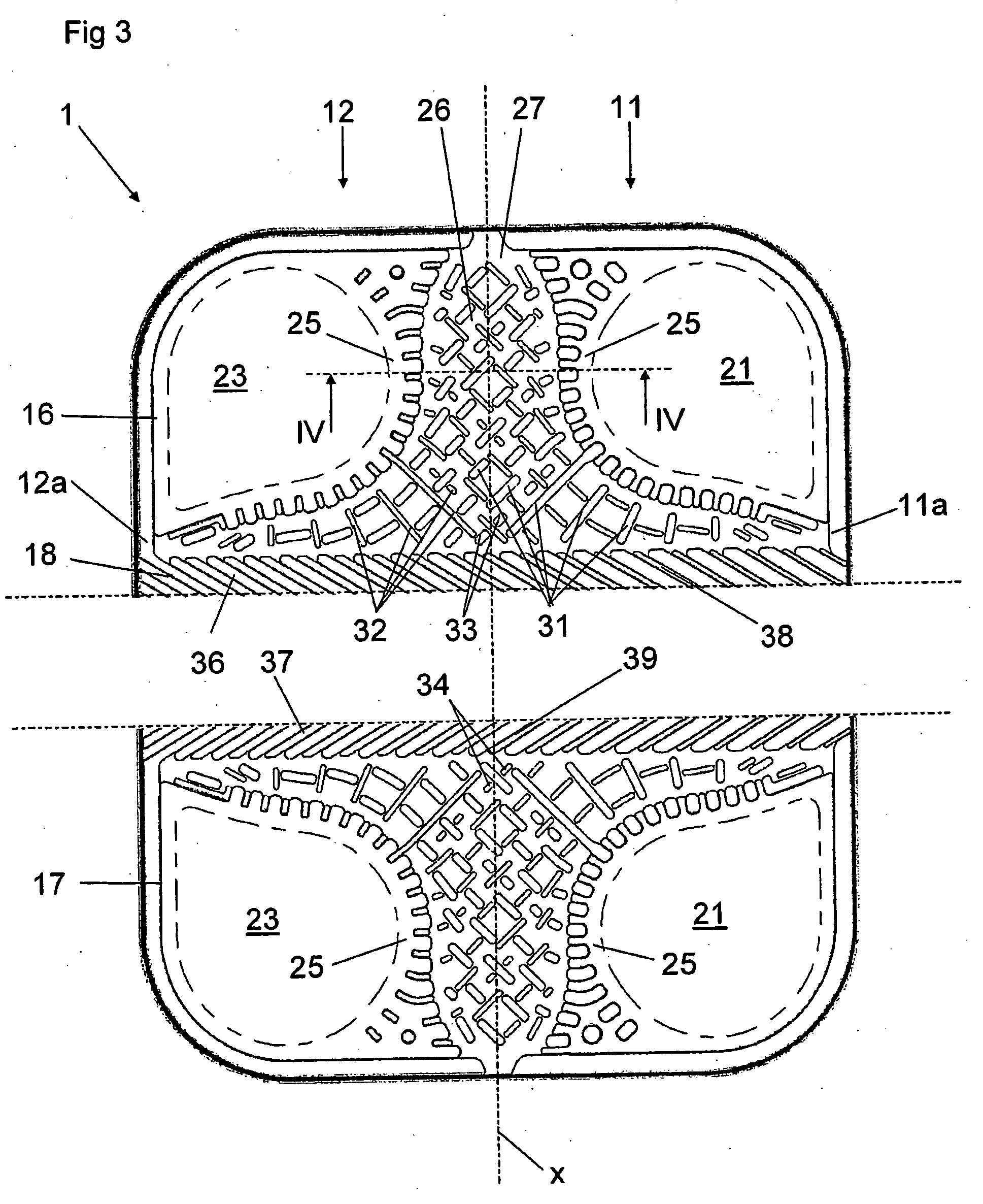
[0029]FIGS. 1 and 2 disclose schematically a plate heat exchanger according to a first embodiment of the invention. The plate heat exchanger includes a number of heat exchanger plates 1, see FIG. 3, which are arranged beside each other in such a way that they form a plate package 2. In the first embodiment, the heat exchanger plates 1 in the plate package 2 are permanently joined to each other through for instance brazing in a manner known per se. The plate heat exchanger includes a first inlet port 4 and a first outlet port 5 for a first medium, and a second inlet port 6 and a second outlet port 7 for a second medium.

[0030]Each heat exchanger plate 1 has in the embodiment disclosed a substantially rectangular basic shape and extends between a primary edge zone 11a and a secondary edge zone 12a in parallel with a central extension plane 13, an upper plate plane 14 and a lower plate plane 15, see FIG. 4. The central extension plane 13 includes a longitudinal centre axis x which divid...


PUM


Abstract

The invention refers to a heat exchanger plate (1) and a plate package for a plate heat exchanger. The heat exchanger plate extends between a primary edge zone (11a) and a secondary edge zone (12a). A centre axis (x) divides the heat exchanger plate in a primary part (11) and a secondary part (12). The heat exchanger plate includes a first end area (16), a second end area (17), and a central heat transfer area (18) therebetween. A primary porthole (21) and a secondary porthole (23) extend through the plate in the first end area and are surrounded by the respective adjoining edge area (25). The primary porthole is located on the primary part and the secondary porthole on the secondary part. A distribution area (26) extends on the first end area and has a base surface (27) extending from the primary porthole to the central heat transfer area. The base surface is inclined and located at an upper level at an upper plane in the proximity of the edge area of the primary porthole and sinks successively to a lower level in the proximity of a lower plate plane at secondary edge zone.

Description

BACKGROUND OF THE INVENTION AND PRIOR ART[0001]The present invention refers to a heat exchanger plate for a plate package for a plate heat exchanger, wherein the heat exchanger plate extends between a primary edge zone and a secondary edge zone in parallel with a central extension plane, an upper plate plane and a lower plate plane, wherein the central extension plane includes a centre axis dividing the heat exchanger plate in a primary part and a secondary part, and wherein the heat exchanger plate includes a first end area, a second end area, a central heat transfer area, which extends between the primary edge zone and the secondary edge zone from the first end area to the second end area, a primary porthole and a secondary porthole, which extend through the heat exchanger plate in the first end area and which are surrounded by a respective adjoining edge area, wherein the primary porthole is located on the primary part and the secondary porthole on the secondary part, and a distr...

Claims


Application Information

Patent Timeline
IPC IPC(8): F28F3/08F28D9/00F28FF28F3/04F28F13/06F28F13/08
CPCF28D9/005F28F9/026F28F3/046F28F3/044
Inventor BJORNSSON, PETER KRISTIANEKELUND, ROLF OLLE
Owner ALFA LAVAL CORP AB
Why Eureka
Try Eureka