Remote pick-up devices

a pickup device and remote technology, applied in the direction of manipulators, load-engaging elements, gripping heads, etc., can solve the problems of unsatisfactory solutions in some applications, inability to conveniently manipulate the locking mechanism of the device, and less favorable ergonomic arrangement, so as to achieve a streamlined device profile and quickly and accurately alter the orientation of the engagement elements.

Active Publication Date: 2008-09-18
ONTEL PRODS
View PDF13 Cites 20 Cited by
  • Summary
  • Abstract
  • Description
  • Claims
  • Application Information

AI Technical Summary

Benefits of technology

[0008]In addition, because conventional pick-up devices as described herein employ extended rods, the packaging, shipping, storage and display of these devices may be inconvenient. The present invention, which involves the combination of a hinge provided at a medial location on the rod and the ability to orient the engagement elements in approximately the same plane in which the handle exists allows the device to be stored in manner where the overall profile of the device is minimized. Thus, depending on the orientation of the rod with respect to he handle, the engagement element may rest either on the lateral sides of the handle or on top section of the handle. When the engagement element are folded in such a manner where the engagement elements are brought into close on the top of the handle the engagement elements are oriented in a plane that is transverse to a plane defined by the handle and trigger. When at rest on the side, the profile of the device is larger than in the alternative arrangement because the outer extension elements that connect the engagement element to the rod extend both above and below the opposite lateral sides of the handle. In the alternative arrangement, theses engagement elements are in a plane that is parallel with that plane defined by the handle and, the total distance comprised of the width of the handle and the width of the engagement elements is reduced.
[0010]Yet a further improvement disclosed herein is the provision of a light in connection with the device. In a preferred embodiment a lamp or LED is positioned at the distal end of the rod and oriented in a manner to allow the illumination of an area near the location that the engagement elements come together. This feature is particularly advantageous when the device is used to retrieve objects that have fallen behind or from underneath furniture or appliances. In these circumstances the ambient lighting near the object that is intended to be retrieved is often poor and providing a light in association with the device assists the user in locating and manipulating the objects. A light is also beneficial when retrieving items from shelves where the ambient lighting is often not optimal. In a preferred embodiment of the device, the light source is positioned within the extended arm or rod thereby maintaining a streamlined profile for the device. This arrangement also allows the device to be used in narrow passages which may not be possible in the event that a light fixture or flashlight was mounted above or below the rod. In addition, the provision of a light source, such as an LED or bulb in at the end of the rod serves to provide a closure to the end of the rod which presents debris from entering the rod and contributes to a more pleasing appearance.
[0011]A further feature of the present invention is the provision of predetermined discrete angular positions that the rod may occupy with respect to the handle. The manner in which the rod is seated typically provides two alternative positions that are positioned ninety degrees with respect to each other. The alternative manners in which the rod is seated provide adequate support to resist the twisting of the rod in the seat when a load or torque force is placed from either the engagement elements or handles. The pre-selected positions that the rod may occupy are also advantageous because it allows the user to quickly and accurately alter the orientation of the engagement elements from alternative positions depending on the desired function or application sought by the user.
[0012]It is therefore a first object of the present invention to provide a manner in which the orientation of the engagement elements may be altered from two pre-selected positions each at angular positions that approximately ninety degrees apart from one another in connection with the elongate engagements tools so that the orientation of the engagement elements may be altered while the orientation of the user's hands may remain unchanged. A further object of the present invention is to provide a light source in the rod section in connection with elongate pick-up tools that also serves as a cap for the rod.

Problems solved by technology

While a user may be able to turn his or her arm to achieve alternative orientations of the engagement elements, this solution may be unsatisfactory in some applications, particularly when the object that is to be engaged is heavy.
When the thumb is used to offset the force, it cannot conveniently be used to manipulate the locking mechanism of the device.
It is submitted that both alternative orientations described above result in a less favorable ergonomic arrangement.
In this application, the engagement elements must be operated in narrow confines and may be limited to orientation in a single plane.
The orientation of the handle so the engagement elements can operate within the confined space may result in an inconvenient position of the handle.
In these applications, if the engagement elements come together in a plane that is transverse to a plane defined by the pistol grip handle, the handle may not fit within the space or the manipulation of the trigger may be inconvenient.
In addition, because conventional pick-up devices as described herein employ extended rods, the packaging, shipping, storage and display of these devices may be inconvenient.
When such devices are oriented in a position wherein the thumb is not positioned on the top of the handle, the distribution of forces on the user's hand and arm are not in an optimal arrangement.
In these circumstances the ambient lighting near the object that is intended to be retrieved is often poor and providing a light in association with the device assists the user in locating and manipulating the objects.

Method used


Image

  • Remote pick-up devices
  • Remote pick-up devices
  • Remote pick-up devices

Examples


Embodiment Construction

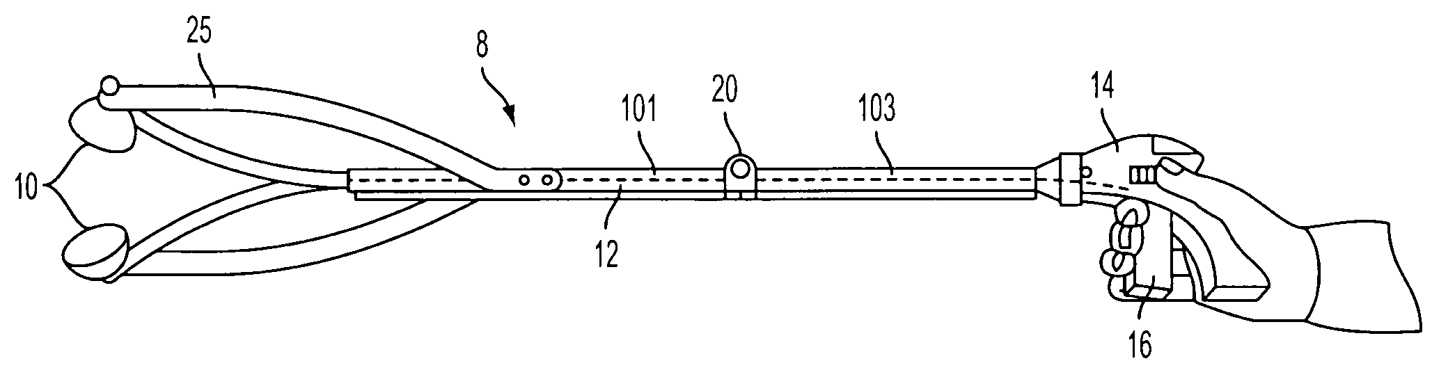
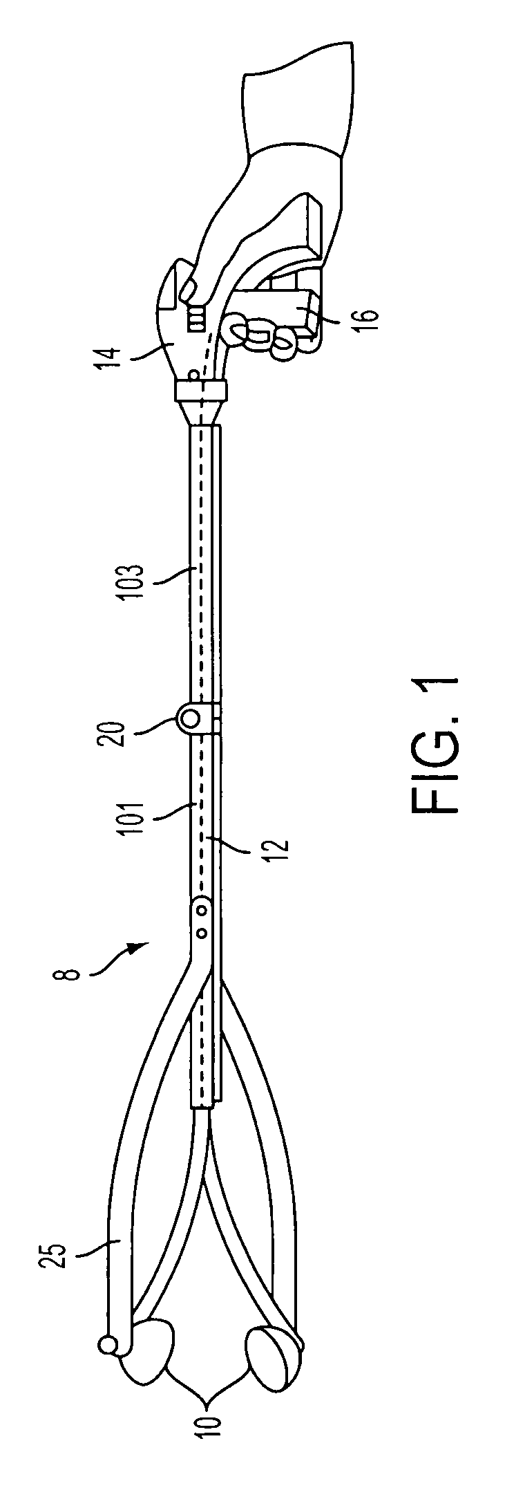
[0032]Now referring to FIG. 1, a first embodiment of the elongate grabber tool 8 is depicted in a first position. Grabber tool 8 incorporates engagement cups 10 on a distal end of an elongate hollow rod 12 and includes a pistol grip 14 on the opposite proximal end. In this embodiment an axial section of rod 12 is rectangular. A trigger 16 is provided adjacent to pistol grip 14 for manipulation by a user's fingers. As shown on the side of pistol grip 14, a switch 18 is provided that effects a locking feature of the engagement elements of the device. In this embodiment at a medial point on elongate hollow rod 12 is hinge 20 that allows the distal portion of the rod 12 to fold in a direction toward the top side of handle 14. Stabilizer prong 25 is attached to the lateral side of the rod 12.

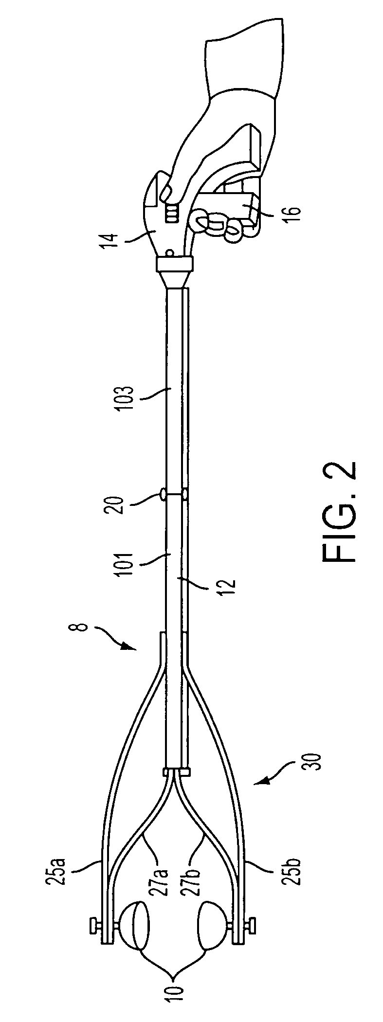
[0033]Now referring to FIG. 2, this depiction shows rod 12 that has been rotated 90 degrees with respect to the pistol grip 14. In this position engagement elements 30 which comprise the cups 10, out...


PUM


Abstract

An improvement to elongate tools for engaging objects from remote distances is disclosed wherein the connection between the rod on which the engagement elements are provided and the handle of the device allows for the orientation of the rod with respect to the handle to occupy at least two pre-selected fixed positions which are at angular positions approximately 90 degrees from one another.

Description

CROSS REFERENCE TO RELATED APPLICATION[0001]The applicant claims the benefit of U.S. Application No. 60 / 989,111 filed on Jan. 30, 2007.BACKGROUND OF THE INVENTION[0002]This invention relates to improvements for tools designed to engage objects from remote distances.BACKGROUND OF THE INVENTION[0003]There are a wide variety of tools designed for picking up objects or manipulating objects from a distance. One common application for such tools is use by maintenance workers to pick up debris for subsequent disposal. A tool with an elongate handle allows manipulation of the object without the need to bend over or to directly handle the material. Such tools are also useful for individuals that have physical handicaps which may impede their ability to bend over and reach the ground. There are also numerous additional household applications for such tools such as retrieval of materials from high shelves, from under furniture, and cooking applications wherein it is desirable to keep away from...

Claims


Application Information

Patent Timeline
Patent Type & Authority Applications(United States)
IPC IPC(8): B25J15/08
CPCB25J1/04
Inventor KHUBANI, ASHOK
Owner ONTEL PRODS
Why Eureka
Try Eureka