Spinal fixation system and method

a technology of fixation system and spine, applied in the field of spine fixation system, can solve the problems that the use of surgical systems often becomes a complex task, and achieve the effect of minimizing the profile of the elongated member

Active Publication Date: 2015-11-17
XTANT MEDICAL HLDG INC
View PDF98 Cites 23 Cited by
  • Summary
  • Abstract
  • Description
  • Claims
  • Application Information

AI Technical Summary

Benefits of technology

[0004]In accordance with one aspect of the present invention, a spinal fixation system is provided that permits a spinal rod to be secured to a pair of pedicle screw assemblies during minimally invasive surgery without the use of pedicle screw yoke extender tubes. Instead, the spinal fixation system comprises two or more pedicle screw assemblies each having an upstanding elongate member for directing the spinal rod as the spinal rod is advanced subcutaneously and secured with the pedicle screw assemblies. The elongate member may be solid, cannulated, or have other cross-sectional configurations, although a solid cross-section permits the profile of the elongate member to be minimized. A distal end of the spinal rod is advanced transversely relative to the elongate members with contact between the spinal rod and the elongate members providing tactile feedback that the spinal rod is positioned adjacent the pedicle screw assemblies. The spinal rod is free to travel along, away from, toward, and around the elongate members such that the spinal rod can be maneuvered to avoid tissues and / or boney structures while seating the spinal rod on the pedicle screw assemblies. In this manner, the spinal rod may be guided into position on the pedicle screw assemblies without having to fit the spinal rod through slots of yoke extender tubes, as in some traditional approaches.
[0005]In another aspect, a spinal fixation system is provided having a pedicle screw assembly with an open seat for receiving a spinal rod, rather than a yoke as in some traditional pedicle screw assemblies. Whereas a traditional pedicle screw assembly yoke has a U-shape with walls that restrict insertion and removal of a spinal rod to generally linear paths between the yoke walls, the open seat of the instant pedicle screw assembly allows the spinal rod to be positioned on the seat using a range of substantially unrestricted insertion paths. In one form, the seat comprises an arm disposed at the base of an elongate member with a planar seating surface for receiving the spinal rod. The spinal rod may be positioned on the seating surface using a number of different paths, including a vertical path generally downward along the associated elongate member, an oblique path generally downward and at an angle to the elongate member, and a horizontal path generally perpendicular to the elongate member. The ability of the seat to accommodate different insertion paths of the spinal rod provides greater flexibility to maneuver the spinal rod around tissues and / or boney structures during minimally invasive surgery. To fix the spinal rod on the seat, a locking cap is slid downward along the elongate member and engaged with a lower portion of the elongate member. The locking cap clamps the spinal rod against the seat and fixes the spinal rod relative to the associated pedicle screw assembly.

Problems solved by technology

Utilizing these surgical systems often becomes a complex task involving a multitude of surgical tools that are repeatedly connected and disconnected to achieve the desired surgical task.

Method used


Image

  • Spinal fixation system and method
  • Spinal fixation system and method
  • Spinal fixation system and method

Examples


Embodiment Construction

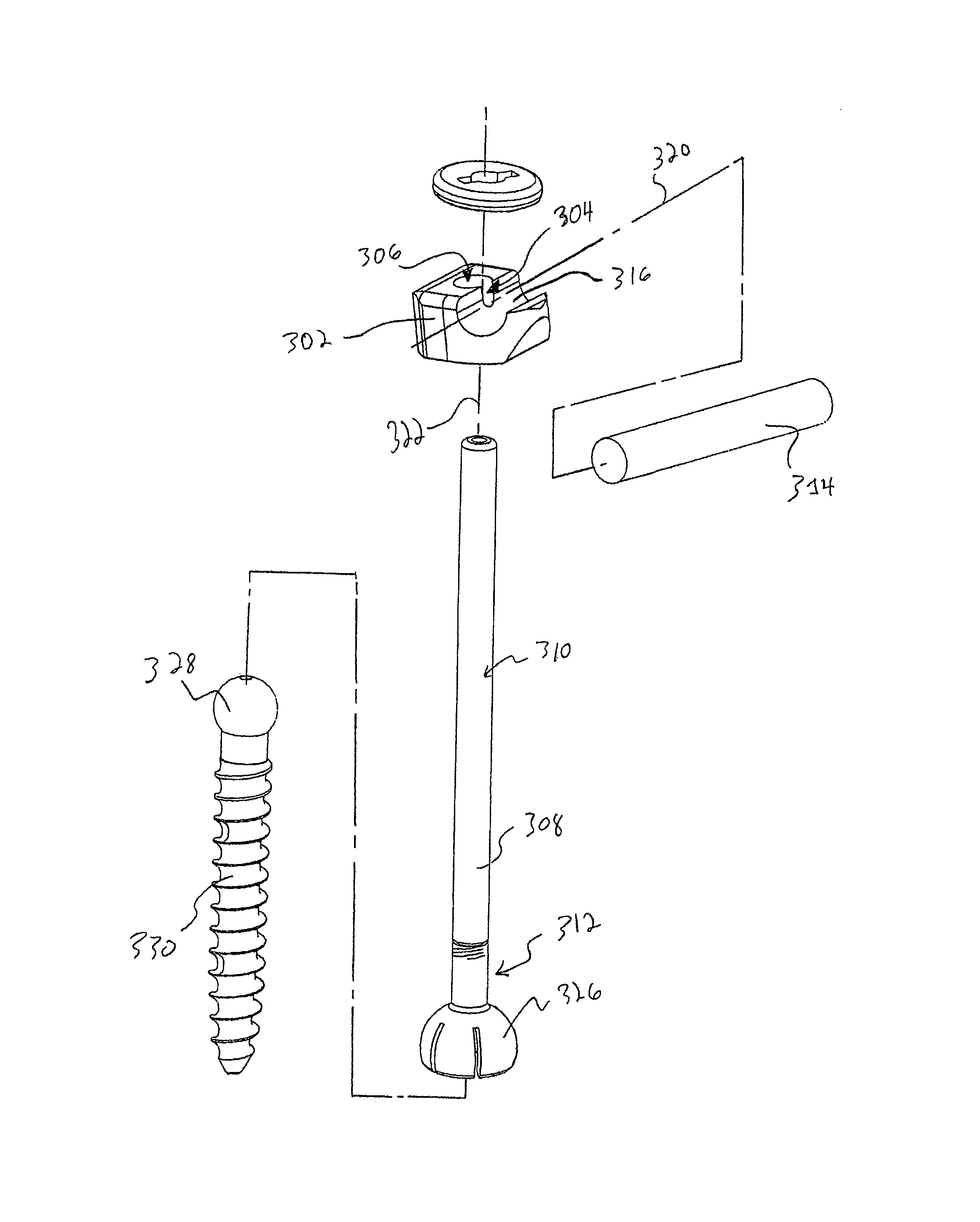
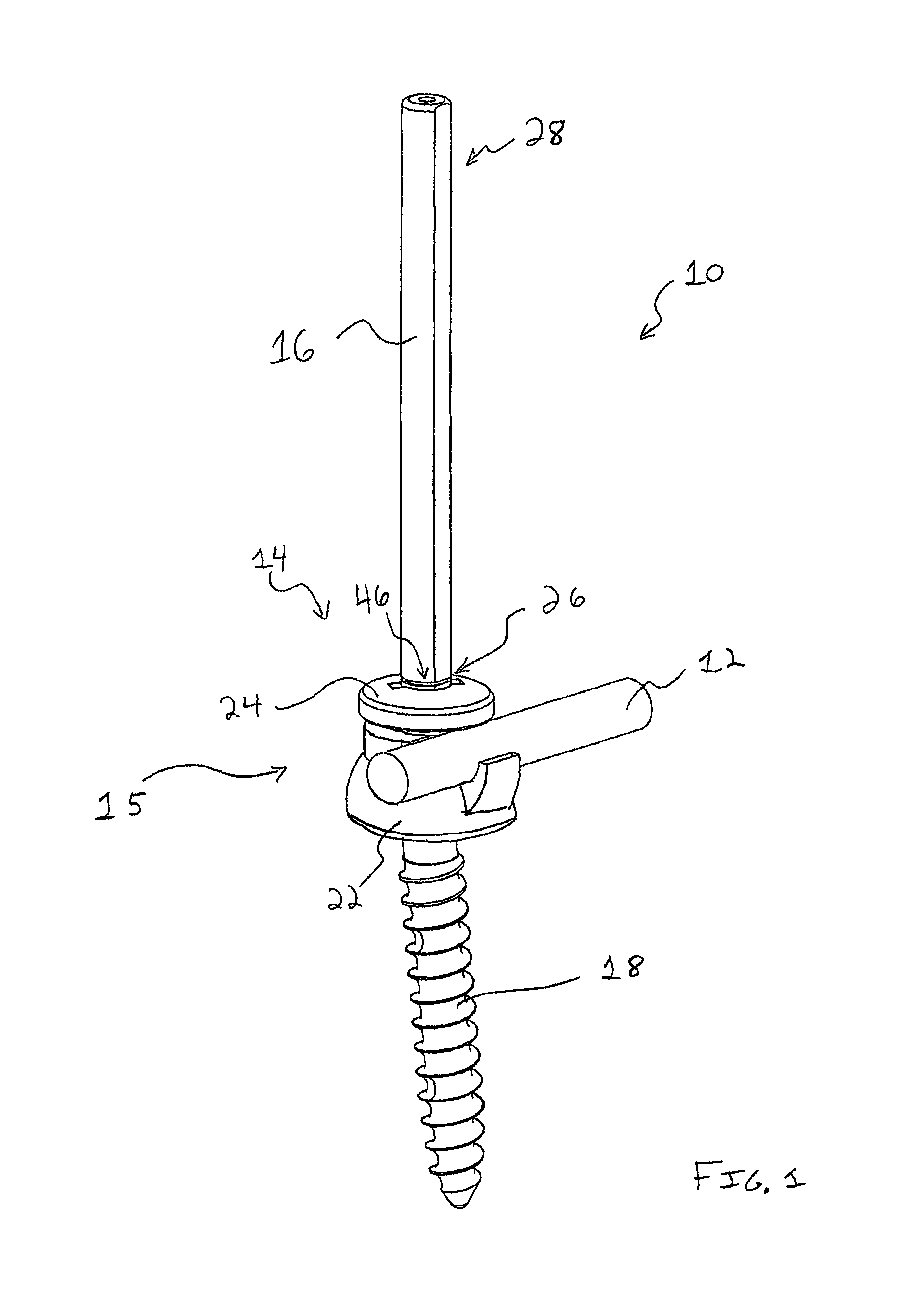
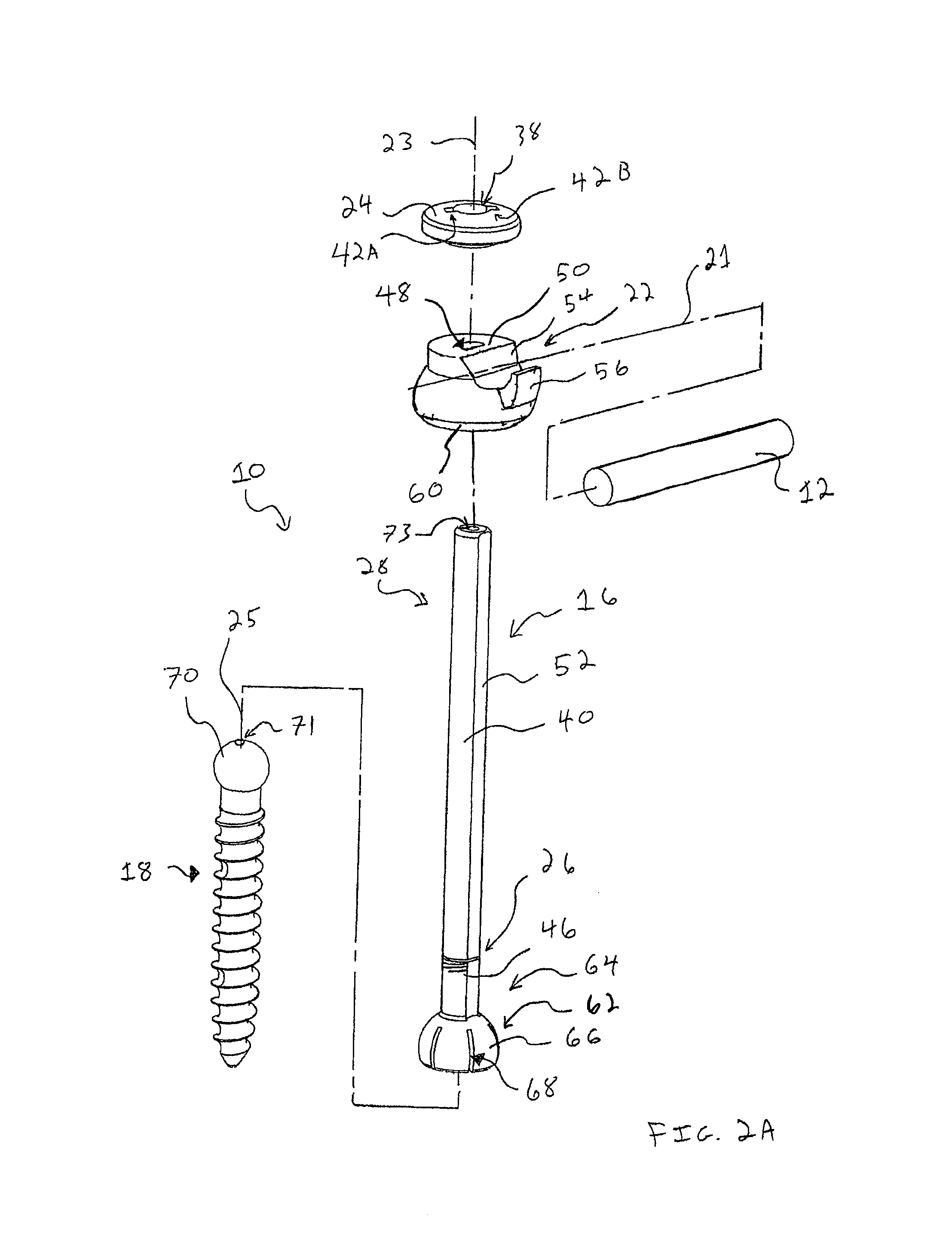
[0039]In FIG. 1, a spinal fixation system 10 in accordance with one form of the present invention is depicted. The spinal fixation system 10 comprises a fixation element, such as a spinal rod 12, and a pedicle screw assembly 14 for securing the spinal rod 12 to a vertebra. The pedicle screw assembly 14 comprises a coupling device 15 and a bone screw 18. The coupling device 15 is operable to secure the spinal rod 12 relative to the bone screw 18. The coupling device 15 has an elongate member, such as guide member 16, for guiding the spinal rod 12 onto an open seat of the coupling device 15, such as a saddle body 22. With the spinal rod 12 received on the saddle body 22, a lock device, such as a locking cap 24, is fit onto and guided down along the guide member 16 and engaged with threads 46 of the guide member 16 to fix the spinal rod 12 against the saddle body 22.

[0040]As can be seen in FIGS. 1 and 2A, the spinal rod 12 rests upon a seating surface 54 of the saddle body 22 generally...


PUM


Abstract

A spinal fixation system is provided that, in one form, comprises a pedicle screw assembly having a coupling device with an elongate member for guiding a fixation element, such as a spinal rod, into the coupling device and a lock device for fixing the spinal rod to the coupling device. The pedicle screw assembly may be passed through a small incision and connected to a vertebral bone. By connecting a second pedicle screw assembly to a second vertebral bone, the elongate members of the pedicle screw assemblies provide guideposts for directing the spinal rod subcutaneously between the pedicle screw assemblies and into the coupling devices thereof.

Description

CROSS-REFERENCE TO RELATED APPLICATION[0001]This application claims the benefit of U.S. Provisional Patent Application No. 61 / 442,617, filed Feb. 14, 2011, which is hereby incorporated by reference in its entirety.FIELD OF THE INVENTION[0002]This invention relates to bone fixation systems and, more particularly, to spinal fixation systems and methods used in minimally invasive procedures.BACKGROUND OF THE INVENTION[0003]Existing minimally invasive surgical techniques include inserting rodding systems through a small incision at the surface of the skin. These surgical techniques often use some form of an extender tube placed over the yoke of the pedicle screw to manipulate positioning of the yoke. The extender tube is also used to pass instruments for persuading the rod, inserting and advancing a locking cap, applying a counter-torque during cap locking, and removing or releasing hardware. These yoke extender tubes typically have slots in their sides to serve as a window to pass the ...

Claims


Application Information

Patent Timeline
Patent Type & Authority Patents(United States)
IPC IPC(8): A61B17/70A61B19/00
CPCA61B17/7038A61B17/7041A61B17/7082A61B17/7085A61B2019/307A61B2090/037
Inventor JANOWSKI, BRIAN P.
Owner XTANT MEDICAL HLDG INC
Why Eureka
Try Eureka