Bone plate system and method

a technology of bone plate and rib, applied in the field of bone plate systems, can solve the problems of irritating the tissues within the chest cavity of patients, the portion of the screw shank to extend beyond the rib, and the retracted rib may not return to the original position, so as to achieve rapid and easy approximation

Active Publication Date: 2016-02-23
A&E ADVANCED CLOSURE SYST LLC
View PDF95 Cites 22 Cited by
  • Summary
  • Abstract
  • Description
  • Claims
  • Application Information

AI Technical Summary

Benefits of technology

[0008]The cable connector devices have opposite end portions with one end portion configured to abut bone adjacent the respective throughbore and the other end portion configured to be operatively fixed to the bone plate member. By utilizing cable connector devices including a cable portion, each cable connector device can be advanced through one of the bone portion throughbores and secured to the bone plate member without exerting outward forces on the bone portion that may fracture the bone portion. Another advantage of this approach is that the cable connector devices eliminates the rigid, complex geometry often present with conventional bone plate / bone screw assemblies. More specifically, the other end portion of the cable connector device may permit the location at which the cable connector device is fixed to the bone plate member to be selected along the cable connector device to permit the orientations of the bone plate member and cable connector assemblies to be conformed to patient anatomy.
[0010]In accordance with another aspect of the present invention, a bone plate system is provided for securing one or more bone portions. The bone plate system includes a connector device having an elongate, flexible portion intermediate leading and trailing end portions of the connector device. The system further includes a plate member having through openings and a locking device associated with the plate member. The locking device has a receiving portion disposed in the plate member throughbore that is sized to permit the leading end portion of the connector device to be advanced therethrough when the locking device is in the unlocked configuration and sized to fix the connector device in the receiving portion when the locking device is in the locked configuration. By positioning the receiving portion in the plate member throughbore, the connector device may be easily advanced into the receiving portion and fixed thereto once the plate member throughbore has been aligned with a bone throughbore. Further, the receiving portion of the locking mechanism provides a lower profile of the bone plate system on the bone when compared to some prior systems where a locking device is located above the plate member which increases the height of those systems.
[0012]In one form, the locking devices of the bone plate system include crimp members having crimpable portions positioned in the through openings of the bone plate between upper and lower surfaces of the bone plate. The crimpable portions have through apertures sized to receive the leading end portions of the connector devices and the crimpable portions may be crimped to fix the crimp members to the connector devices. By positioning the crimpable portions within the through openings of the plate member, the crimp members can be contained substantially entirely within the profile of the bone plate while still permitting rapid connection of the bone plate to the connector devices. Further, the trailing end portions of the connector devices may include plugs configured to engage the pre-drilled holes. The plugs may have outer surfaces that are generally even with or below the outer surface of the bone surrounding the pre-drilled holes when the trailing end portions of the connector devices are secured to the bones. Thus, the compact configuration of the crimp members and the bone plate, in combination with the plugs of the connector devices, minimizes the profile of the bone plate system on both sides of the bones once the bone plate system has been secured to the bones.
[0014]The method further includes tensioning the surgical cable such that the stabilization member redirects the tension force in the surgical cable and pulls the trailing end portion of the surgical cable and the displaced bone connected thereto toward the non-displaced bone. This approach permits the bones to be rapidly and easily approximated by tensioning the surgical cable. In one form, the method further includes reconfiguring a locking device of the stabilization member to a locked configuration to fix the second end of the stabilization member to the surgical cable connected to the displaced bone such that the stabilization member is secured to the bones. This provides a secure construct of the stabilization member and the bones and utilizes a single surgical cable to both approximate the bones and fix the stabilization member to the bones.
[0015]In one approach, the non-displaced bone is a first rib and the displaced bone is a second rib that has been retracted away from the first rib during a thoracotomy procedure. The method includes forming a hole in the second rib before or after retraction that is spaced away from a neurovascular bundle running along the underside of the second rib. The method further includes advancing a leading end portion of a surgical cable through the hole in the second rib and tensioning the surgical cable to draw a plug on a trailing end portion of the surgical cable into engagement with the second rib to connect the trailing end portion of the surgical cable to the second rib. In this manner, the surgical cable can be connected to the second rib without pinching or otherwise damaging the neurovascular bundle thereof.

Problems solved by technology

However, rib bones are relatively thin such that driving the screws into the portions of the cut rib exerts an outward pressure upon the bone which may splinter the bone.
This may cause a portion of a screw shank to extend beyond the rib and irritate tissues within the chest cavity of the patient.
The retracted ribs may not return to their original position after the retraction device has been removed, which may be due to breaking of the surrounding bones and / or cartilage.
However, each rib has a delicate neurovascular bundle of a vein, an aertery, and a nerve extending along the underside of the rib such that tightening the looped suture wire around the ribs may undesirably pinch the neurovascular bundle of one or more of the ribs.
One problem with this approach is that drilling the pilot holes in the rib portions may be difficult because the rib portions are hard to manipulate after being cut.
Another problem is that obtaining a precise alignment of the pilot holes in the rib portions and the throughbores of the bone plate is challenging due to the difficulty in drilling properly spaced and oriented pilot holes in the cut rib portions.

Method used


Image

  • Bone plate system and method
  • Bone plate system and method
  • Bone plate system and method

Examples


Embodiment Construction

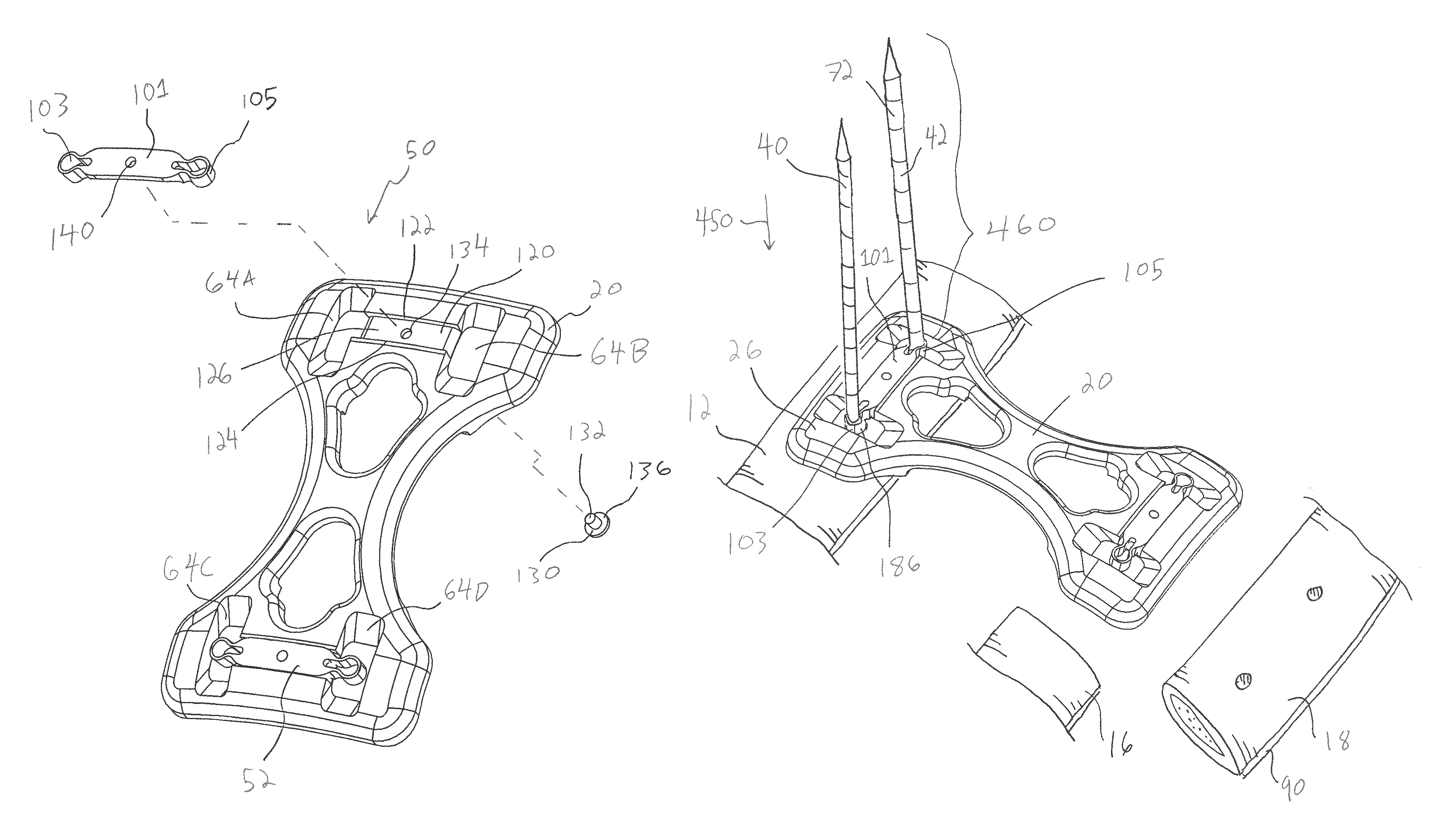
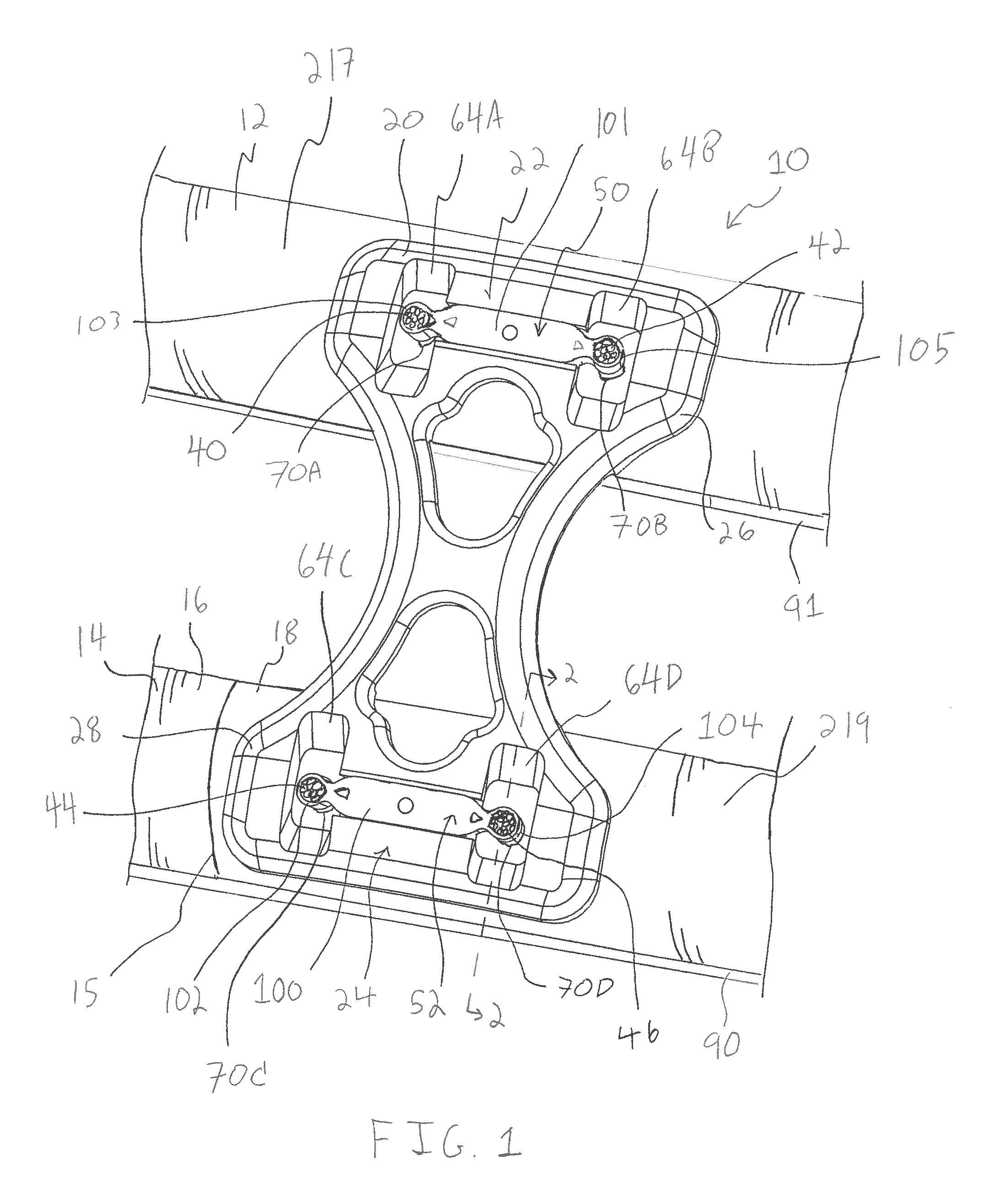
[0086]Referring to FIG. 1, a bone plate system 10 is provided for stabilizing one or more bones, such as ribs 12, 14, after the rib 14 has been cut such as along cut line 15 into two portions 16, 18 as part of a thoracotomy procedure. The bone plate system 10 includes a stabilizing member, such as bone plate 20, sized to extend between the ribs 12, 14 and keep the rib portion 18 relatively stable and in proximity to the rib portion 16. This decreases the relative movement between the rib portions 16, 18 due to breathing and movement of the patient and may improve post-operative fusion between the rib portions 16, 18.

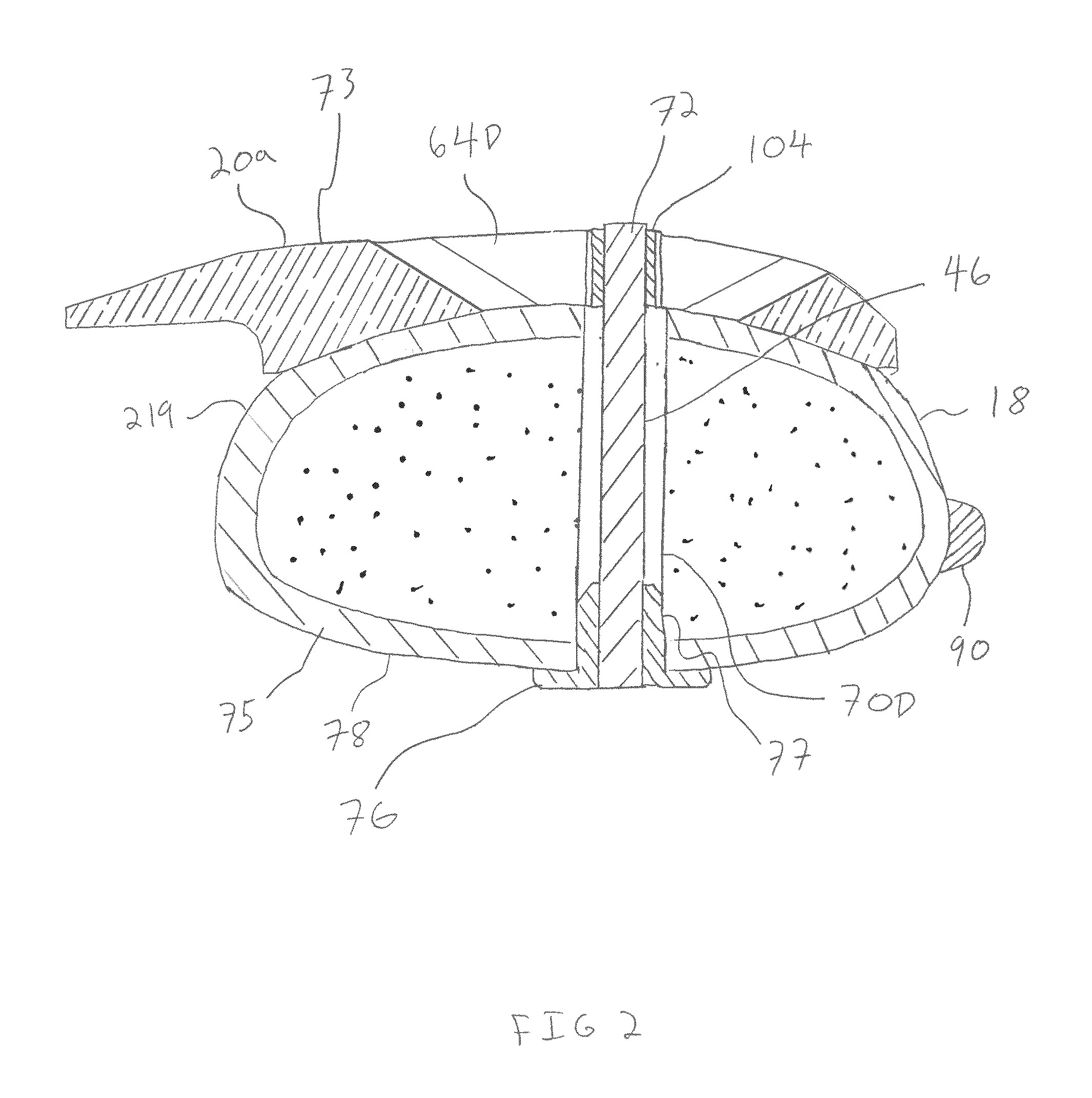
[0087]The bone plate 20 includes locking devices 22, 24 at opposite ends 26, 28 thereof for fixing the plate 20 at its ends 26, 28 to connector devices that may include cable portions. One example of these connector devices are surgical cables 40, 42, 44 and 46, as shown in FIGS. 1, 2, 2A, and 2B. In one form, the locking devices 22, 24 include crimp assemblies 50, 52 fo...


PUM


Abstract

In one aspect, a bone plate system is provided including a bone plate and a plurality of cable connector devices configured to be inserted into throughbores formed in bone portions and through openings of the bone plate member aligned therewith. The cable connector devices each include opposite end portions with one end portion configured to abut against the bone adjacent the throughbore and the other end portion configured to be operatively fixed to the bone plate member with the cable portion extending therebetween and in the bone throughbore for securing the bone plate member to the bone portion with the cable connector devices including a cable portion thereof extending in the bone throughbore.

Description

CROSS-REFERENCE TO RELATED APPLICATIONS[0001]This application claims the benefit of U.S. Provisional Patent Application No. 61 / 580,560, filed Dec. 27, 2011, and U.S. Provisional Patent Application No. 61 / 710,354, filed Oct. 5, 2012, which are both hereby incorporated by reference in their entireties.FIELD OF THE INVENTION[0002]The invention relates to bone plate systems and, more particularly, to a bone plate system for stabilizing one or more bones.BACKGROUND OF THE INVENTION[0003]There are presently many different types of bone plate systems for securing bones so that the secured bones may fuse or heal. As used herein, the term bone may refer to a bone, a bone fragment, or a portion of a bone. One application for bone plate systems is repairing one or more ribs after a thoracotomy. A thoracotomy may involve cutting a rib or, in some instances, removing a section of a rib in order to provide access to tissues and organs within the chest cavity of a patient.[0004]After the tissues o...

Claims


Application Information

Patent Timeline
Patent Type & Authority Patents(United States)
IPC IPC(8): A61B17/80A61B17/82A61B17/84
CPCA61B17/8076A61B17/809A61B17/8052A61B17/823A61B17/842
Inventor GEPHART, MATTHEW, P.
Owner A&E ADVANCED CLOSURE SYST LLC
Why Eureka
Try Eureka