Low profile spinal fixation system

a low-profile, spinal fixation technology, applied in the field of spinal fixation systems, can solve the problems of inability to fix the entire system, the size or profile of the coupler as well as the compression member is increased, and the entire system is undesirably larg

Inactive Publication Date: 2006-11-28
PIONEER SURGICAL TECH INC
View PDF216 Cites 273 Cited by
  • Summary
  • Abstract
  • Description
  • Claims
  • Application Information

AI Technical Summary

Benefits of technology

[0005]In accordance with the present invention, a low-profile spinal fixation system is provided. In one aspect, a cam lock member of a coupling device is fixed against translation as it is turned so that a cam surface of the lock member causes an elongate member that extends generally along the spinal column, e.g. spinal rod, to be forced or pushed downward. As the cam lock member does not translate along the coupling device, the size of the coupling device can be kept to a minimum. Further, the low profile of the present system may allow for minimally invasive surgical procedures to be employed therewith such as with the components thereof being cannulated for use with a guide wire.
[0006]In another aspect, a polyaxial spinal fixation system is provided having a coupling member including an internal seat surface and a central bore sized to allow the anchor member to extend through the bore in several different orientations. The anchor member includes a head having an upper recess in which a low profile insert is provided. The insert has an upper surface that may be substantially flat, may have radially oriented concave paths or valleys so that the insert rotates to the closest path to meet with the spinal rod, or may have a cup or peripheral ridge that deforms when compressed by the spinal rod to form a path without deforming the spinal rod. The upper surface is fit in the head recess with the insert sized so that the upper surface projects only slightly beyond the proximal end of the anchor member to keep the profile of the insert to a minimum.
[0007]In a preferred form, the insert has an enlarged lower portion having a lower arcuate surface thereon for bearing against the concave recess surface of the anchor member head, and a central projection that extends upwardly from the lower portion and includes the flat upper surface thereon. The anchor member head preferably includes a retainer such as in the form of staked portions that allow the insert to self-adjust as the angle of the coupling member is adjusted with the flat surface projecting above the anchor member head for engaging the spinal rod.

Problems solved by technology

The problem with the threaded or cam wedge systems of spinal rod locking is that to allow the compression member to advance relative to the coupler, the size or profile of the coupler as well as the compression member necessarily is increased.
However, the entire Errico et al. system has a undesirably large profile as it employs a threaded set screw for clamping on the spinal rod, and the hemispherical insert extends well beyond the top of the screw head into the coupler channel through which the spinal rod is received.

Method used


Image

  • Low profile spinal fixation system
  • Low profile spinal fixation system
  • Low profile spinal fixation system

Examples


Embodiment Construction

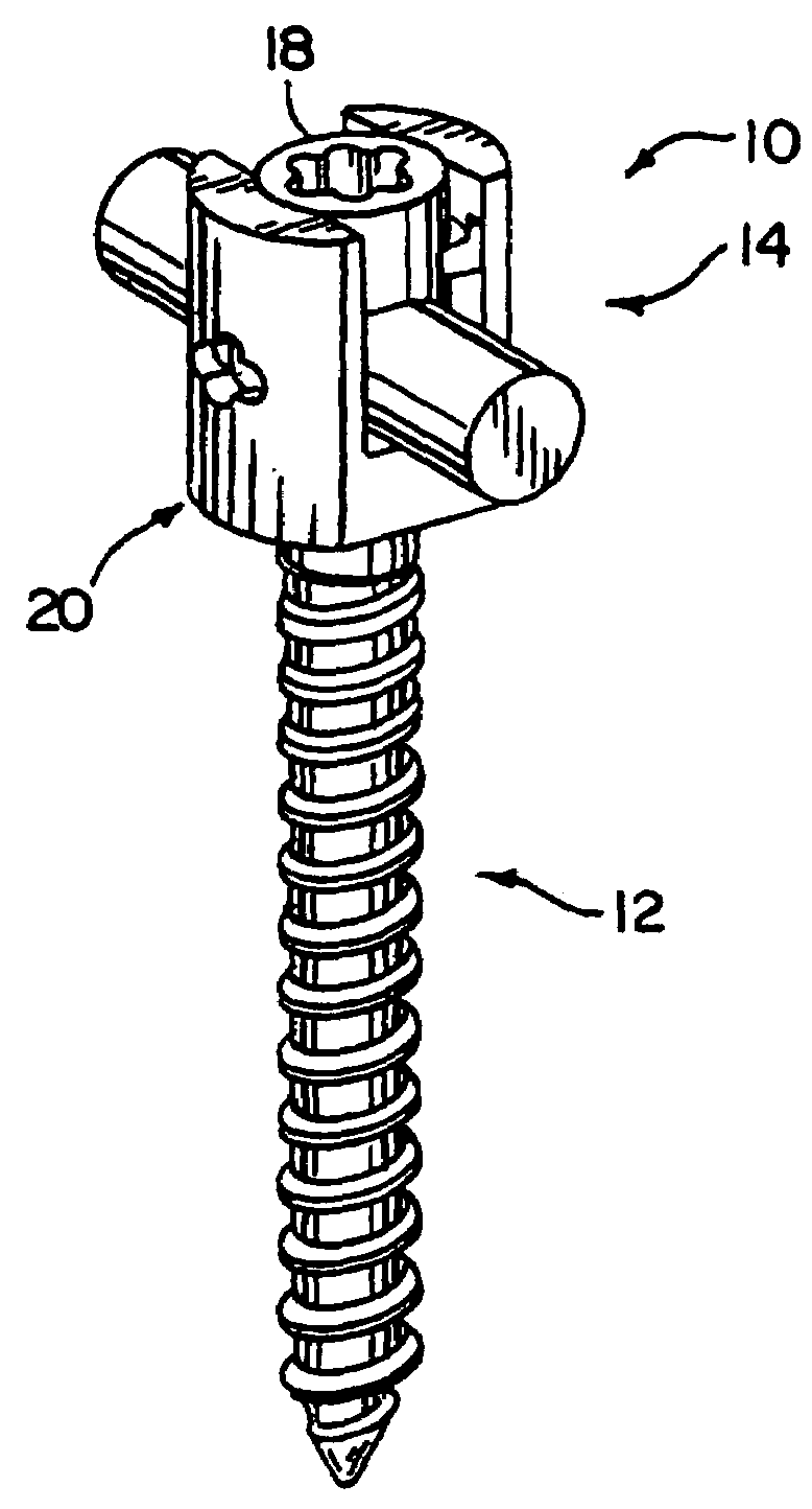
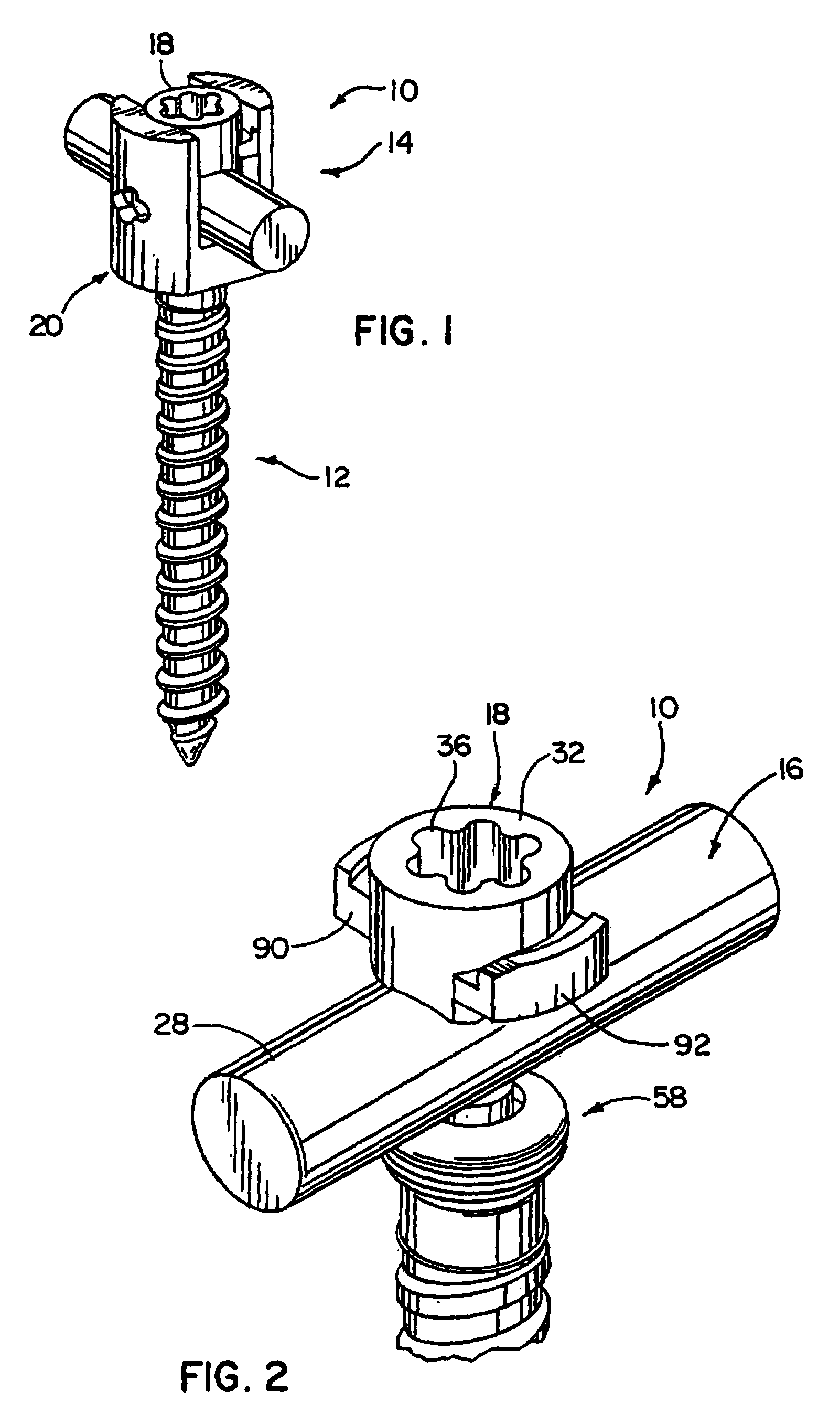
[0018]In FIGS. 1 and 2, a low profile spinal fixation system 10 in accordance with the present invention is depicted. As shown, the spinal fixation system 10 includes a bone anchor member in the form of a bone screw 12 and a coupling device generally designated 14. The coupling device 14 is operable to secure an elongate member in the form of spinal rod 16 in place relative to the bone screw 12. The coupling device 14 includes a compression or cam lock member 18 and a coupling member 20, which cooperate to secure the spinal rod 16 relative to the bone screw 12 anchored in a vertebral bone with the rod 16 generally extending axially along the spinal column. The coupling device 14 and specifically the cam lock member 18 and coupling member 20 are provided with a compact configuration. In particular, the cam lock member 18 and coupling member 20 are provided with a very low profile in a direction indicated by axis line 21 extending transverse and specifically orthogonally to the axis 1...


PUM


Abstract

A spinal fixation system is provided that, in one form, includes a coupling member having a cam lock member that is fixed against translation as it is turned with turning of the cam lock member causing an elongate member such as a spinal rod to be pushed downward in the coupling member for fixing the rod therein. In another aspect, the rod is fixed against a low profile insert that seats in a recess formed in the head of an anchor member projecting from the coupling member. The insert has an upper surface against which the rod is fixed. In one form, the insert upper surface is flat to provide for line contact against the rod so as to minimize damage thereto. In another form, the cam lock member cams against a clamping member driving it downward in the coupling member for fixing the rod therein.

Description

FIELD OF THE INVENTION[0001]The invention relates to spinal fixation systems and, more particularly, to spinal fixation systems that have a low profile.BACKGROUND OF THE INVENTION[0002]Spinal rods for immobilizing vertebral bones of the spinal column are typically anchored to the vertebrae via bone screws that extend through the pedicle into the vertebral bodies or by hooks that engage about the vertebrae. The rods are connected to the anchor members by generally yoke-shaped couplers that can be either integral with the anchor member head or separate components from the anchor member for use in polyaxial pedicle screw systems for spinal rod fixation. These prior systems employ some sort of compression member that is brought down into engagement either directly or indirectly with the spinal rod for securing it relative to the anchor member, and in polyaxial systems for securing the anchor member relative to the coupler.[0003]For this purpose, the compression member and coupler typica...

Claims


Application Information

Patent Timeline
Patent Type & Authority Patents(United States)
IPC IPC(8): A61B17/58A61B17/70
CPCA61B17/7032A61B17/7037
Inventor JANOWSKI, BRIAN P.KORHONEN, FRANCIS J.KILPELA, THOMAS S.
Owner PIONEER SURGICAL TECH INC
Why Eureka
Try Eureka