Electrical connector having low broad mounting profile

Inactive Publication Date: 2010-07-08
HON HAI PRECISION IND CO LTD
View PDF13 Cites 21 Cited by
  • Summary
  • Abstract
  • Description
  • Claims
  • Application Information

AI Technical Summary

Benefits of technology

[0009]In order to achieve the object set forth, an electrical connector, which is adapted for mounting to a circuit board, has a mounting foot with a top mounting surface, a elongated base portion protruded outwardly from said top mounting surface and two fittin

Problems solved by technology

As the time goes by, the popularity of these devices has risen as the cost and the sizes of the devices have diminished, and low profile is naturally required for electrical connector to

Method used


Image

  • Electrical connector having low broad mounting profile
  • Electrical connector having low broad mounting profile
  • Electrical connector having low broad mounting profile

Examples


Embodiment Construction

[0017]Reference will now be made in detail to the preferred embodiment of the present invention.

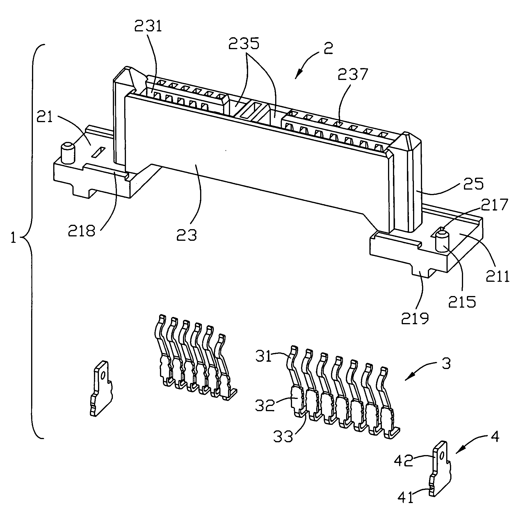
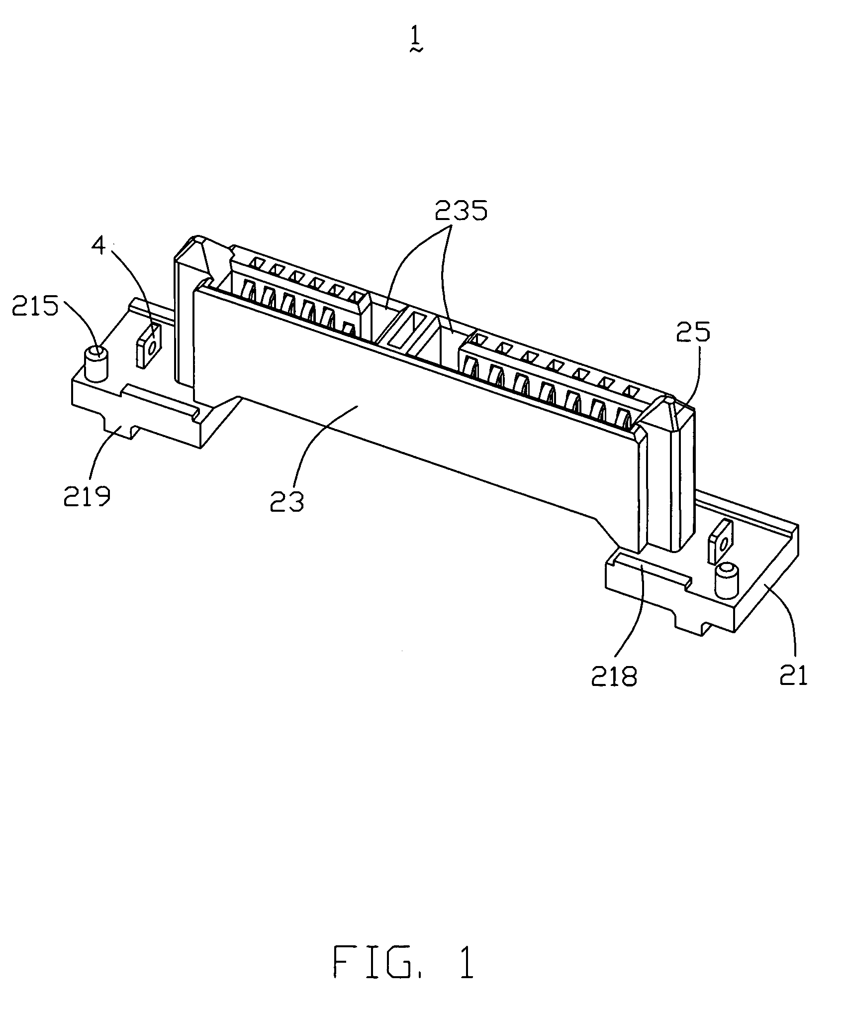
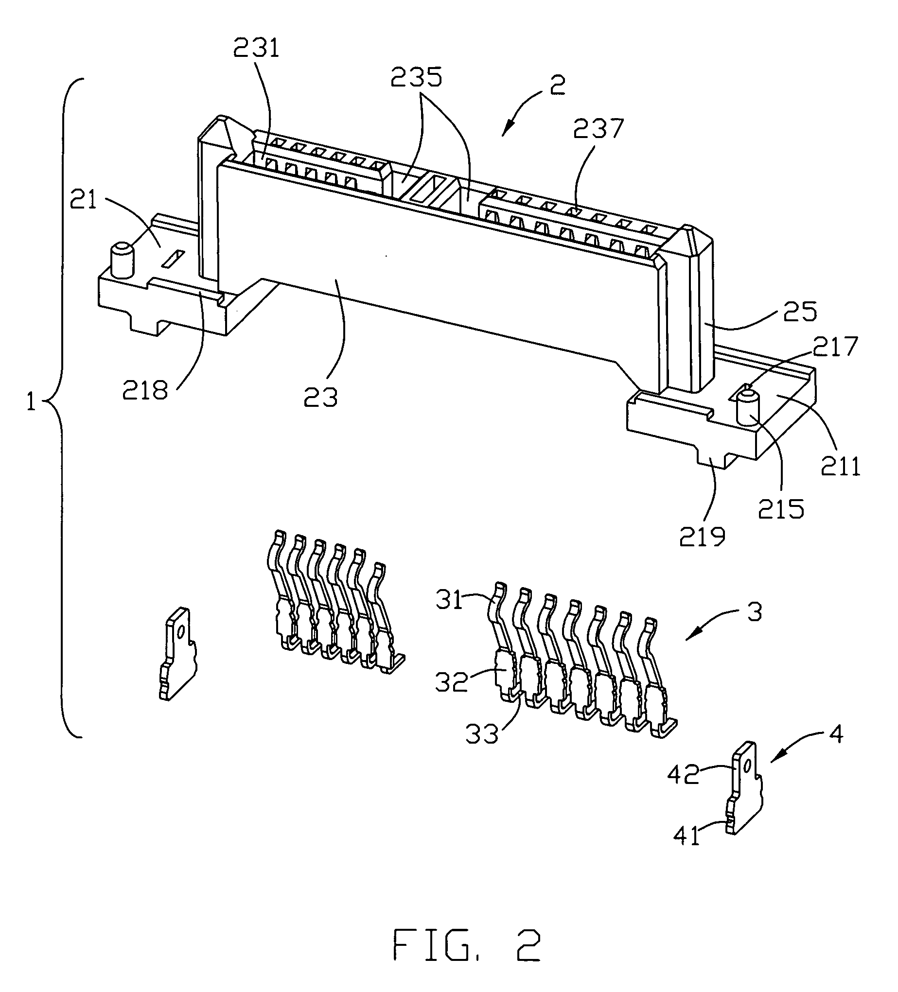
[0018]Referring to FIGS. 1-6, an electrical connector 1 for mounting on a circuit board 5 in accordance with the embodiment of the present invention comprises an insulated housing 2, a plurality of terminals 3 received in said insulated housing 2, and two fitting members 4 assembled onto the insulated housing 1.

[0019]Referring to FIGS. 1-3, a mounting foot 21 is formed on said insulated housing 2, the mounting foot 21 engages a top mounting surface 211 for mounting said electrical connector 1 to a circuit board 5 and a back surface 213 opposite and parallel to the top mounting surface 211. An elongated base portion 23 with a mating head and a bottom-end opposite to the mating head is protruded outwardly from said top mounting surface 211, and two L-shaped mating slots 235 are hollowed on the base portion 23 vertical to the top mounting surface 211. Said electrical connector 1 comprises a ...


PUM


Abstract

An electrical connector (1), which is adapted for mounting to a circuit board (5), has a mounting foot (21) with a top mounting surface (211), an elongated base portion (23) protruded outwardly from said top mounting surface (211) and fitting members (4) set on the top mounting surface (211). In assembly, the top mounting surface (211) is face to the back of the circuit board (5), and the whole mounting foot (21) is left below the circuit board (5), which can minimize the mounting profile of the connector (1) effectively.

Description

BACKGROUND OF THE INVENTION[0001]1. Field of the Invention[0002]The present invention relates to an electrical connector, and more particularly, to an electrical connector mounted from a bottom surface of a printed circuit board so as to reduce the overall height exposed above a top surface of the same.[0003]2. Description of Related Art[0004]In the last decade, electrical connectors are widely used in electronic devices, such as notebooks. As the time goes by, the popularity of these devices has risen as the cost and the sizes of the devices have diminished, and low profile is naturally required for electrical connector to meet the reduced sizes of the equipments said above.[0005]T.W. Pat. No. 510588 issued on Nov. 11, 2002 discloses a related board end connector. Said electrical connector includes a base portion, a number of contacts received in the base portion, a guiding block on each one of two opposite side faces of the base portion for guiding the connector to mate with a mat...

Claims


Application Information

Patent Timeline
IPC IPC(8): H01R13/40
CPCH01R13/74H01R12/7052H01R12/714
Inventor YANG, SHENG-HOYANG, CHUN-CHIEH
Owner HON HAI PRECISION IND CO LTD
Why Eureka
Try Eureka