Grout cleaning apparatus

Inactive Publication Date: 2008-09-25
KORDICK ERIC
View PDF13 Cites 18 Cited by
  • Summary
  • Abstract
  • Description
  • Claims
  • Application Information

AI Technical Summary

Benefits of technology

[0006]In accordance with an embodiment of the present invention, an improved grout cleaning apparatus is disclosed. The apparatus comprises, in combination: a shaft having a first end and a second end; a grip coupled at the first end of the shaft; a cleaning housing coupled at the second end of the shaft; and two inline cleaning wheels positioned within the cleaning housing.
[0007]In accordance with a further embodiment of the present invention, an improved grout cleaning apparatus is disclosed. The apparatus comprises, in combination: a shaft having a first end and a second end; grip coupled at the first end of the shaft; a cleaning housing coupled at the second end of the shaft; inline cleaning wheels positioned within the cleaning housing; wherein each of the inline cleaning wheels has a brush positioned therearound; and a drive motor adapted to drive the two inline cleaning wheels; wherein the drive motor is adapted to drive one of the cleaning wheels in a clockwise direction and an other of the cleaning wheels in a counterclockwise direction.
[0008]In accordance with a still further embodiment of the present invention, an improved grout cleaning apparatus is disclosed. The apparatus comprises, in combination: a sha

Problems solved by technology

It has a tendency to absorb surface dirt, and to become discolored in the process of doing so.
That discoloration can be unsightly, and can harm the appearance of an otherwise attractive tile floor.
Cleaning tile grout can be labor-intensive and physically challenging.
These approaches may be inefficient, may damage the g

Method used


Image

  • Grout cleaning apparatus
  • Grout cleaning apparatus
  • Grout cleaning apparatus

Examples


Embodiment Construction

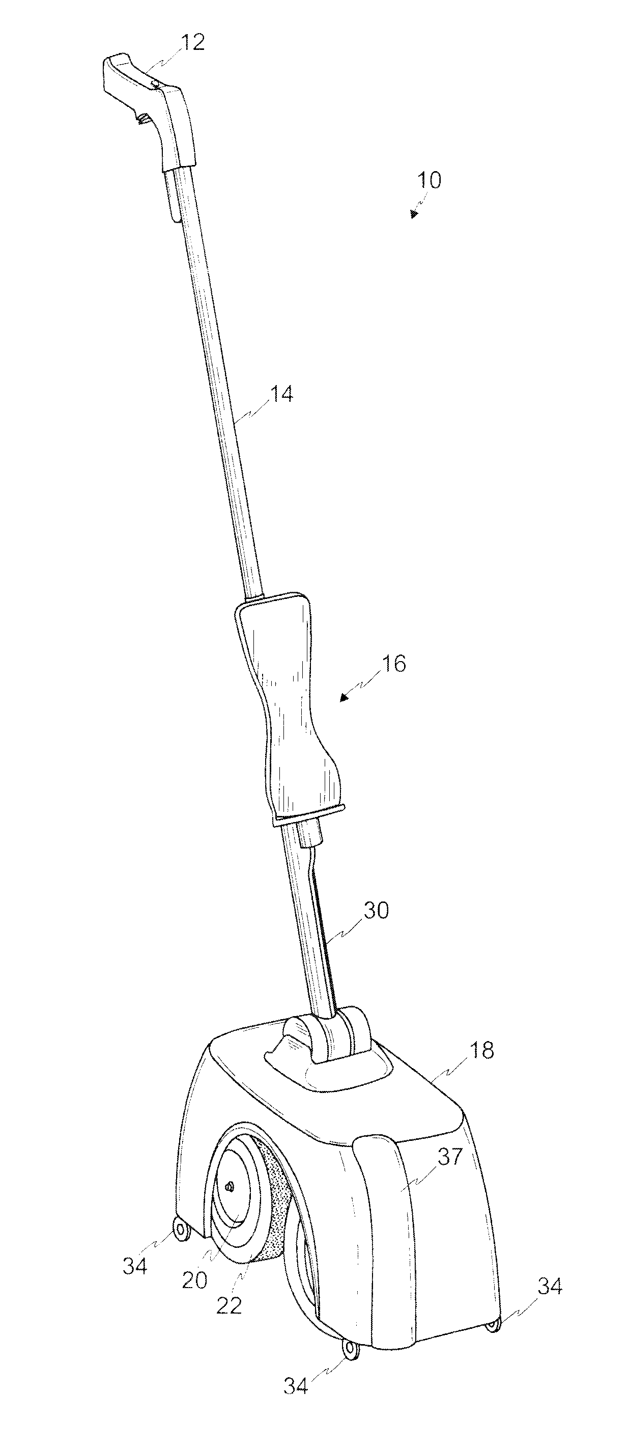
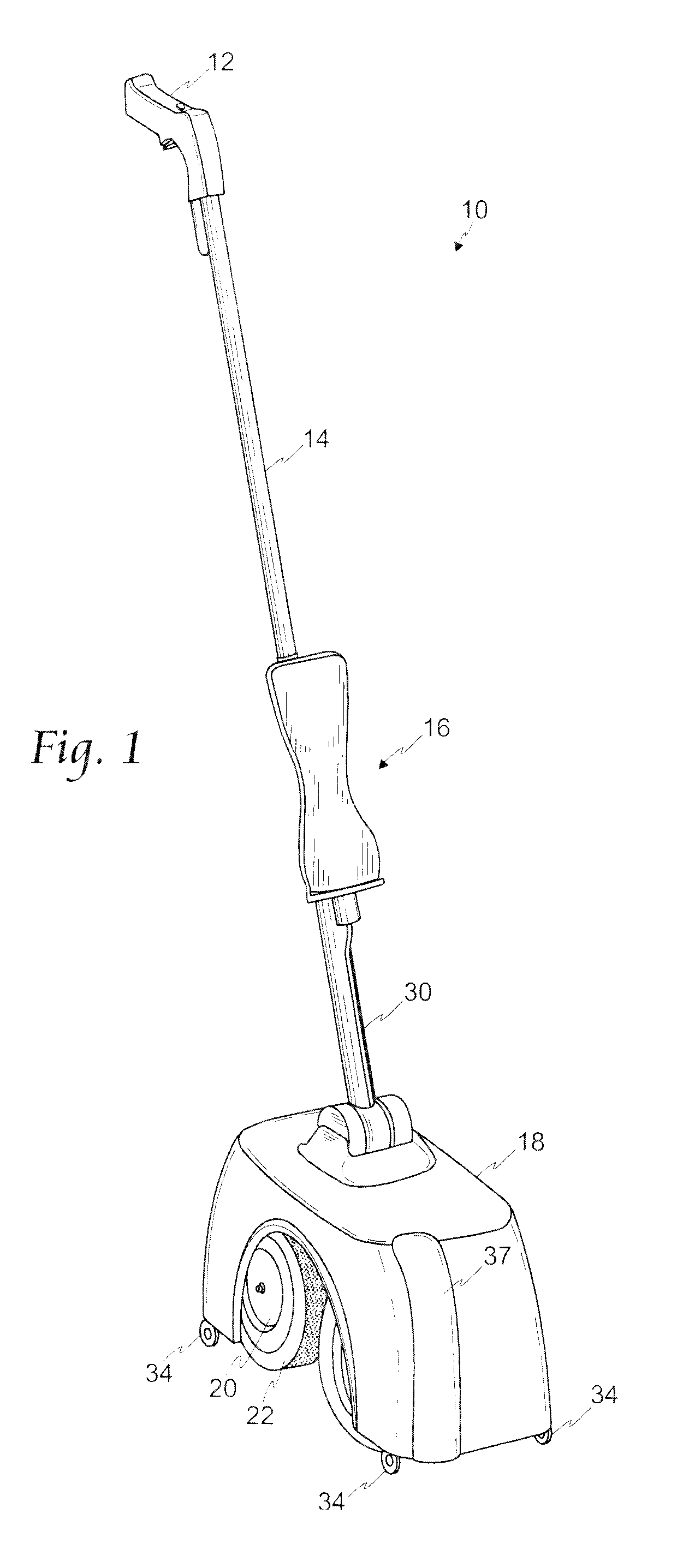
[0019]Referring first to FIG. 1, a grout cleaning apparatus 10 (“apparatus 10”) consistent with an embodiment of the present invention is illustrated. In this embodiment, the apparatus 10 generally comprises a grip 12 coupled to an upper portion of a shaft 14 and a cleaning housing 18 coupled to a lower portion of the shaft 14.

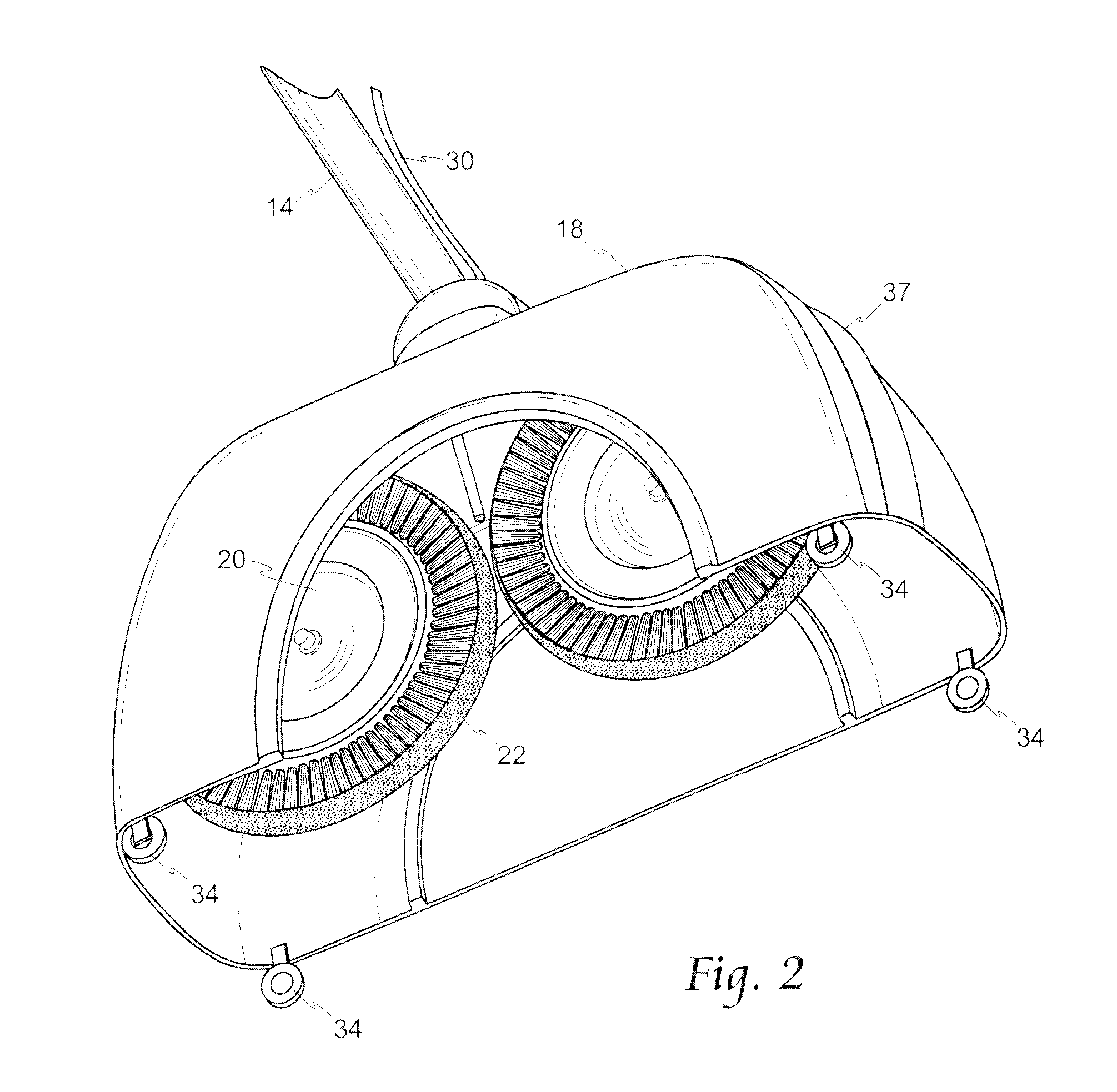
[0020]The shaft 14, which may optionally be adjustable in length, is intended to permit a user to operate the apparatus 10 while in a standing position. Coupling between the shaft 14 and housing 18, as shown in FIGS. 8-10, is preferably at a pivoting, multi-directional joint 11 wherein the shaft 14 is inserted into a ball 15, which ball 15 is retained within a ball housing 17 on the housing 18. The joint 11 is intended to permit a user to operate the apparatus 10 in difficult to reach locations, for example, near cabinet kick boards.

[0021]Turning more specifically to FIGS. 2-3 and 5, retained within the cleaning housing 18 are two inline cleaning wheels 20. Th...


PUM


Abstract

An improved grout cleaning apparatus has in line cleaning wheels positioned within a housing, at the terminus of a shaft. A grip is coupled at an upper end of the shaft, and may be grasped by a user to move the apparatus for cleaning purposes. In one embodiment, a drive motor supplies power to the in line cleaning wheels, which may be made to turn in opposing directions so as to provide improved cleaning efficiency. A cleaning fluid dispenser may also provided on the shaft, to permit the dispensing of fluid proximate the cleaning wheels during operation.

Description

RELATED APPLICATION[0001]This non-provisional application claims priority to provisional application No. 60 / 919,560, filed Mar. 23, 2007.FIELD OF THE INVENTION[0002]The present invention relates generally to the cleaning of tile grout and, more particularly, to an improved grout cleaning apparatus.BACKGROUND OF THE INVENTION[0003]Tile grout is known to be a repository of dirt. It has a tendency to absorb surface dirt, and to become discolored in the process of doing so. That discoloration can be unsightly, and can harm the appearance of an otherwise attractive tile floor.[0004]Cleaning tile grout can be labor-intensive and physically challenging. Many grout cleaning methods require a user to kneel on the floor, and to manually scrub the grout surface, with a toothbrush-type device or sponge, to obtain a cleaning benefit. These approaches may be inefficient, may damage the grout, and / or may be physically uncomfortable for certain persons, and may create an unwanted exposure to contac...

Claims


Application Information

Patent Timeline
IPC IPC(8): A47L11/16A47L11/03A47L11/283
CPCA46B5/0012A46B7/04A46B11/001A46B11/0065A47L13/26A46B13/04A46B2200/3033A47L13/10A46B13/008
Inventor KORDICK, ERIC
Owner KORDICK ERIC
Why Eureka
Try Eureka