Imaging lens, camera module, and portable terminal apparatus

a technology of imaging lens and portable terminal, applied in the field of fixed-focus imaging lenses, can solve the problems of insufficient image forming performance and compactness, and achieve the effect of reducing overall length and high image forming performan

Inactive Publication Date: 2008-10-02
TIANJIN OFILM OPTO ELECTRONICS CO LTD
View PDF1 Cites 17 Cited by
  • Summary
  • Abstract
  • Description
  • Claims
  • Application Information

AI Technical Summary

Benefits of technology

[0011]The present invention has been made in view of the above problems, and an object of the invention is therefore to provide an

Problems solved by technology

Although the lenses disclosed in the above Patent documents employ a three-lens structure and asphe

Method used


Image

  • Imaging lens, camera module, and portable terminal apparatus
  • Imaging lens, camera module, and portable terminal apparatus
  • Imaging lens, camera module, and portable terminal apparatus

Examples


examples

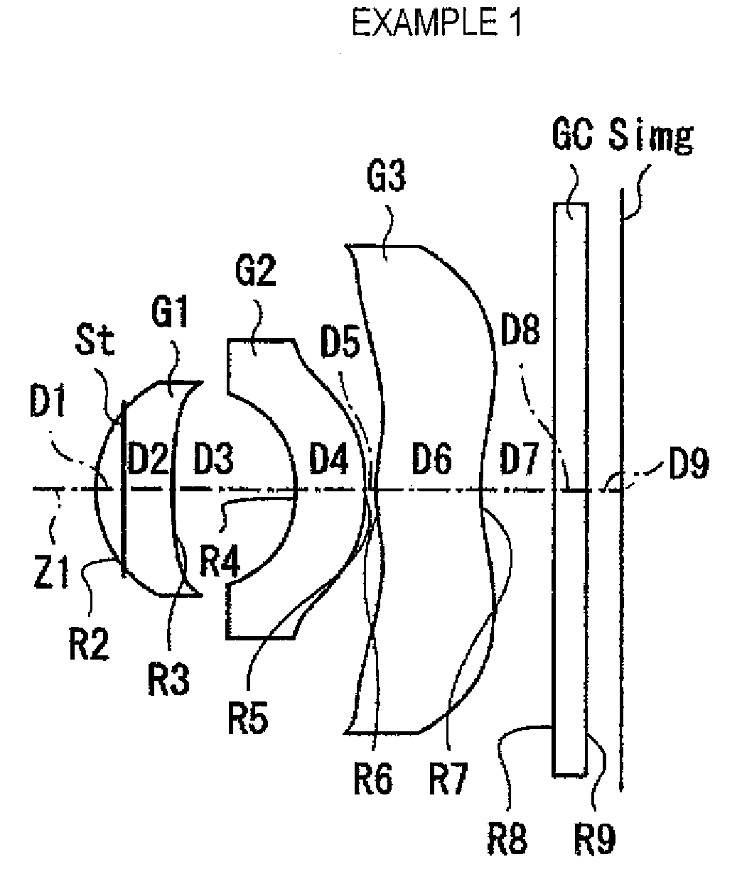
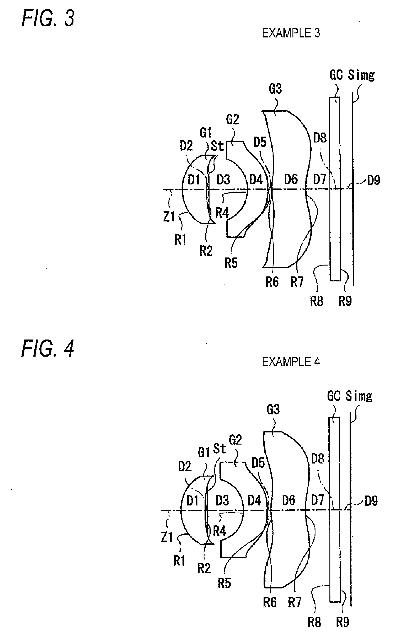
[0073]Next, a description will be made of specific numerical examples of the imaging lens according to the embodiment. In the following, first to seventh numerical examples will be described together.

[0074]Specific lens data of Example 1 which corresponds to the imaging lens configuration of FIG. 1 are shown in FIGS. 8 and 9. FIG. 8 shows lens data and FIG. 9 shows data of the aspheric surfaces. In the lens data of FIG. 8, surface numbers i (i=1-9) which are numbered in such a manner that the optical element closest to the object is given the number “1” and the number increases in order as the position comes closer to the imageside are shown in the column of the surface number Si. The values (mm) of radii of curvature of the respective surfaces (surface numbers 1-9) are shown in the column of the radius Ri of curvature (the meaning of symbol Ri is the same as in FIG. 1). In the column of the on-axis surface spacing Di, the value (mm) of an on-axis spacing between the ith surface Si ...


PUM


Abstract

An imaging lens comprises, in order from an object side: a first lens having a positive refractive power and a meniscus shape and having a convex surface directed to the object side; a second lens having a negative refractive power in the vicinity of an optical axis of the imaging lens; and a third lens having a positive refractive power in the vicinity of the optical axis, wherein at least one surface of each of the second lens and the third lens is an aspheric surface; and the imaging lens satisfies the following conditional expression expressions:
0.7<|f1/f|<0.8   (1)
0.3<|f2/f|<0.8   (2)
75<νd1<96   (3)
TL/2Y<0.9   (4)
where
f: focal length of the imaging lens;
f1: focal length of the first lens;
f2: focal length of the second lens;
νd1: Abbe number of the first lens for the d-line;
    • TL: length between the object-side surface of the first lens to an image forming position of the imaging lens; and
Y: maximum image height.

Description

BACKGROUND OF THE INVENTION[0001]1. Field of the Invention[0002]The present invention relates to a fixed-focus imaging lens which is suitable for use in small imaging apparatus as exemplified by digital cameras using an imaging device such as a CCD (charge-coupled device) or a CMOS (complementary metal oxide semiconductor) sensor and cameras using a silver salt film.[0003]The invention also relates to a camera module which converts an optical image formed by the above imaging lens into an imaging signal and to a portable terminal apparatus such as a cell phone with a camera or a personal digital assistant (PDA) which incorporates the above imaging lens and performs shooting.[0004]2. Description of the Related Art[0005]In recent years, with the spread of personal computers to homes etc., digital still cameras (hereinafter referred to simply as digital cameras) capable of inputting image information obtained by shooting a scene, a person, or the like to a personal computer have spread...

Claims


Application Information

Patent Timeline
IPC IPC(8): G02B13/18
CPCG02B9/16G02B13/0035G02B13/18
Inventor SATO, KENICHITANIYAMA, MINORU
Owner TIANJIN OFILM OPTO ELECTRONICS CO LTD
Why Eureka
Try Eureka