3D Image Generation and Display System

Inactive Publication Date: 2008-10-09
YAPPA CORP
View PDF3 Cites 176 Cited by
  • Summary
  • Abstract
  • Description
  • Claims
  • Application Information

AI Technical Summary

Benefits of technology

[0030]The 3D image generation and display system of the present invention can configure a computer system that generates 3D objects to be displayed on a 3D display. The3D image generation and display system has a simple construction employing a scanning table system to model an object placed on a scanning table by collecting images around the entire periphery of the object with a single camera as the turntable is rotated. Further, the 3D image generation and display system facilitates the generation of high-quality 3D objects by taking advantage of commo

Problems solved by technology

However, since the entire periphery of the object cannot be rendered in three dimensions with the light-sectioning method, it is necessary to collect images around the entire periphery of the object by provid

Method used


Image

  • 3D Image Generation and Display System
  • 3D Image Generation and Display System
  • 3D Image Generation and Display System

Examples


first embodiment

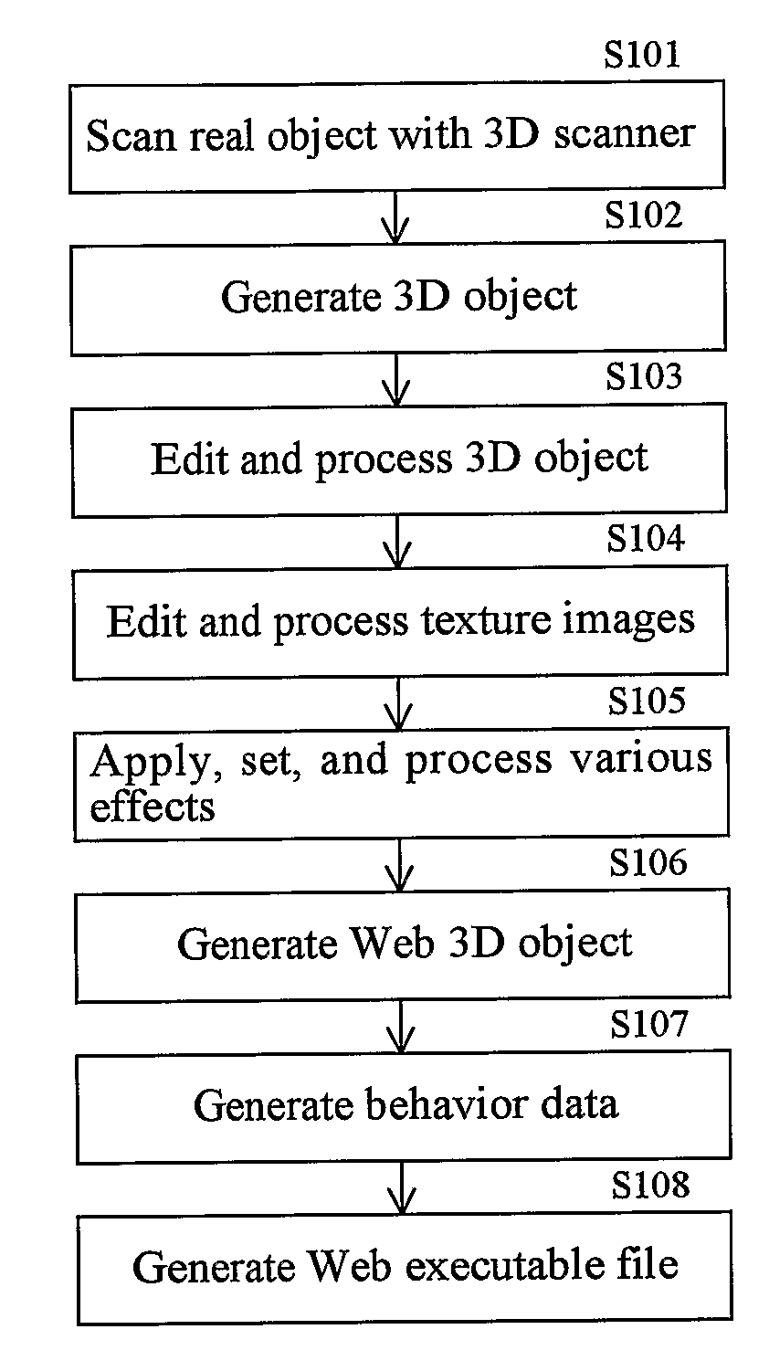
[0034]FIG. 1 is a flowchart showing steps in a process performed by a 3D image generation and display system according to the present invention.

[0035]In the process of FIG. 1 described below, a 3D scanner described later is used to form a plurality of 3D images. A 3D object is generated from the 3D images and converted to the standard Virtual Reality Modeling Language (VRML; a language for describing 3D graphics) format. The converted 3D object in the outputted VRML file is subjected to various processes for producing a Web 3D object and a program file that can be executed in a Web browser.

[0036]First, a 3D scanner of a 3D object generating means employing a digital camera captures images of a real object, obtaining twenty-four 3D images taken at varying angles of 15 degrees, for example (S101). The 3D object generating means generates a 3D object from these images and 3D description file outputting means converts the 3D object temporarily to the VRML format (S102). 3D ScanWare (pro...

second embodiment

[0060]Next, the present invention will be described while referring to the accompanying drawings.

[0061]FIG. 5 is a schematic diagram showing a 3D image generation and display system according to a second embodiment of the present invention. The second embodiment further expands the 3D image generation and display system to allow the 3D images generated and displayed on a Web page in the first embodiment to be displayed as stereoscopic images using other 3D display devices.

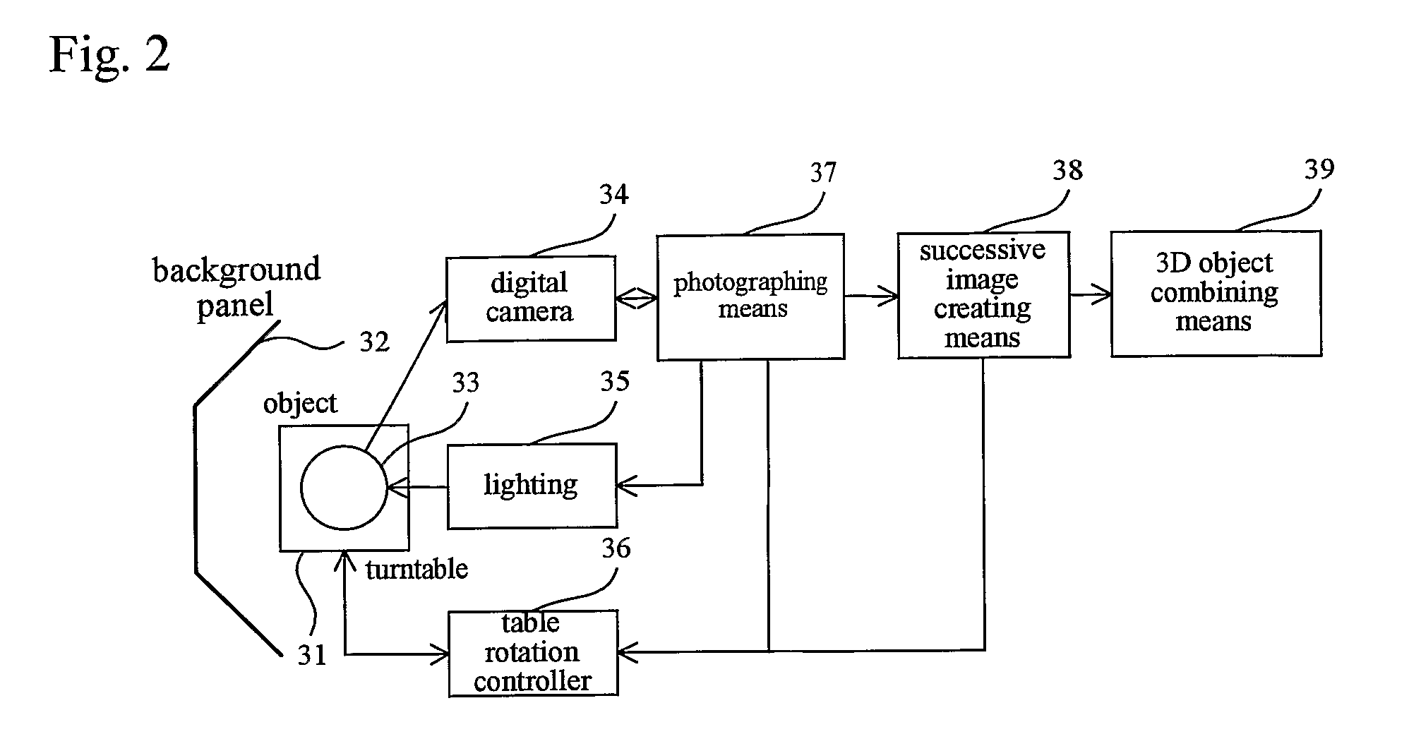
[0062]The 3D image generation and display system in FIG. 5 includes a turntable-type 3D object generator 71 identical to the 3D object generating means of the first embodiment shown in FIG. 2. This 3D object generator 71 produces a 3D image by combining images of an object taken with a single camera while the object is rotated on a turntable. The 3D image generation and display system of the second embodiment also includes a multiple camera 3D object generator 72. Unlike the turntable-type 3D object generator 71, t...


PUM


Abstract

A 3D image generation and display system facilitating the display of high-quality images in a Web browser comprises means for creating 3D images from a plurality of different images and computer graphics modeling and generating a 3D object from these images that has texture and attribute data; means for converting and outputting the 3D object as a 3D description file in a 3D graphics descriptive language; means for extracting a 3D object and textures from the 3D description file, setting various attribute data, and editing and processing the 3D object to introduce animation or the like and assigning various effects; means for generating various Web-based 3D objects from the 3D data files produced above that are compressed to be displayed in a Web browser and generating behavior data to display 3D scenes in a Web browser with animation; and means for generating an executable file comprising a Web page and Web-based programs such as scripts, plug-ins, and applets for drawing and displaying 3D scenes in a Web browser.

Description

CROSS-REFERENCE TO RELATED APPLICATIONS[0001]The present Application is based on International Application No. PCT / JP2005 / 008335, filed on Apr. 25, 2005, and priority is hereby claimed under 35 USC §119 based on this application. This application is hereby incorporated by reference in its entirety.TECHNICAL FIELD[0002]The present invention relates to a 3D image generation and display system that generates a three-dimensional (3D) object for displaying various photographic images and computer graphics models in 3D, and for editing and processing the 3D objects for drawing and displaying 3D scenes in a Web browser.BACKGROUND ART[0003]There are various systems well known in the art for creating 3D objects used in 3D displays. One such technique that uses a 3D scanner for modeling and displaying 3D objects is the light-sectioning method (implemented by projecting a slit of light) and the like well known in the art. This method performs 3D modeling using a CCD camera to capture points or...

Claims


Application Information

Patent Timeline
IPC IPC(8): G06T15/00G06T15/10H04N13/221
CPCG06T15/10G06T19/00H04N13/0221H04N13/0242H04N13/0253H04N13/0404H04N13/0409H04N13/0422H04N13/0452H04N13/0459H04N13/305H04N13/243H04N13/221H04N13/254H04N13/324H04N13/356H04N13/31H04N13/363
Inventor ITO, MASAHIRO
Owner YAPPA CORP
Why Eureka
Try Eureka